IPCP Pro Series • Hardware Features and Installation 34
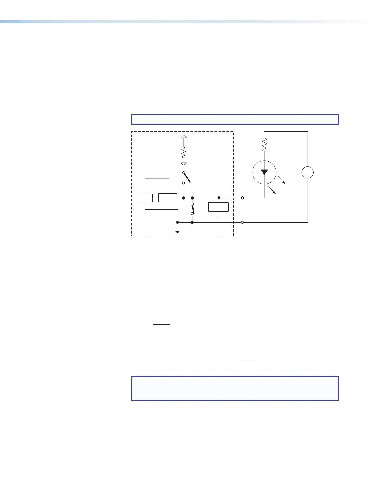
• Flex I/O digital output with pull-up disabled
• When switch 1 closes, the port is on and the front panel LED is on.
• When switch 1 opens, the port is off and the front panel LED is off.
• Example application, digital output without pull-up: connecting an LED
and an external +5VDC power source
This application often requires a current-limiting resistor, as shown in the
diagram below. Many button switches that contain LEDs have a resistor built in.
See the guide for the lighted switch or stand-alone LED for details.
NOTE: Each flex I/O pin is capable of sinking a maximum of 250 mA.
+
-
+5.0 V
1k ohms
SW 2
SW 1
Flex
I/O
GND
Voltage
Protection
A/D
Converter
CTL
LED
Externa
+5 VDC
Power
Source
Resistor
(R)
Figure 31. Flex I/O Digital Output Application:
LED and External +5VDC Power Source Without Pull-up
To determine the value of the current limiting resistor in the circuit shown above,
you need to know the values of three variables:
i = LED forward current in amps (found in the data sheet for the LED)
V
f
= LED forward voltage drop in volts (found in the data sheet for the LED)
V
s
= supply voltage of the external voltage source
Insert those values into the following equation to determine the resistor value:
s
f
Example calculation:
i = 5 mA (0.005 A)
V
f
= 2 V
V
s
= 5 V
NOTE: If the value calculated for the current limiting resistor is not a
standard resistor value, you can round up the number to the next highest
common resistance value.
The connected LED is off when the port (switch 1) is open.
The connected LED is on when the port (switch 1) is closed.
}
=
=
s
f