IPCP Pro Series • Hardware Features and Installation 36
I
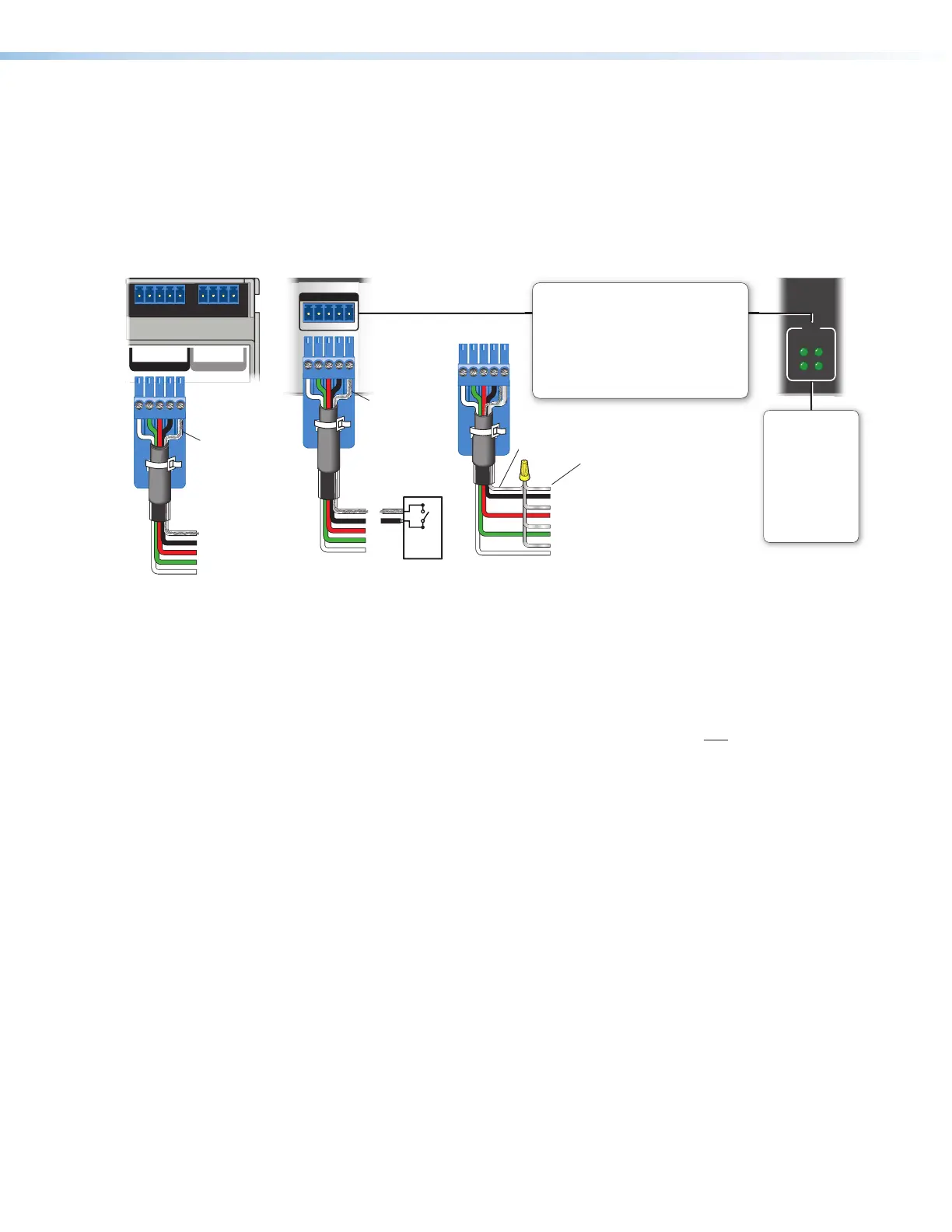
Digital I/O (digital input/output) ports — These ports work the same way the flex
I/O ports work, but they do not offer analog input, and thresholds are not adjustable.
Connect physical switches, sensors, LEDs, relays, or similar items to these ports (see
figure 14, figure 15, and figure 16 on page18 through page20), which can be
configured as digital inputs or outputs, with or without +5VDC pull-up. These ports can
trigger events or functions (such as triggering relays, issuing commands, or sending an
e-mail) that have been set up using Global Configurator.
1234G
DIGITAL I/O
1 234G
DIGITAL I/O
eBUS
+V +S -S G
PWR OUT = 6W
I/O
3
1
4
2
Rear Panel,
Rack Mount Models
Rack Mount
Models
Digital I/O LEDs
Light when the
corresponding ports
are active.
For digital input
On: logic low
Off: logic high
For digital output
On: port is on
Off: port is off
Switch,
Sensor
2
1
3
4
G
Heat
Shrink
Over
Shield
Wires
(Switches, sensors,
LEDs, relays, or
similar items)
Ground
Share the same ground
among I/O connections.
Device 4
Device 3
Device 2
Device 1
Wire
Nut
Digital I/O (digital input/output)
Congure each port as a digital input or output,
with or without +5 VDC pull-up. Use these
ports to:
• Monitor or trigger events and functions (toggle
relays, issue commands, send e-mail), once
congured.
• Power LEDs or other devices that accept a
TTL signal.
Front/Top Panel,
DIN Rail Models
2
3
4
G
Heat Shrink
Over
Shield Wires
Figure 33. Digital I/O Port Wiring Examples
Digital input — To allow the IPCP to monitor external devices that do not use RS-232
communication, connect a switch, motion sensor, moisture sensor, tally feedback
output, button pad, or a similar item to a digital I/O port and configure it for digital input.
When configured as a digital input, the port is set to measure two states: high and low.
The port accepts 0 to 25.3 VDC input.
Unlike flex I/O ports, for digital I/O ports, threshold voltages are not adjustable.
Thresholds are:
• 2.0VDC — port on, logic low
• 2.8VDC — port off, logic high
There is also an internal, selectable, pull-up resistor connected to +5VDC, which you
can use if the connected device does not provide its own power.
Rev. G:
Added details
about LED
behavior for
digital I/O ports