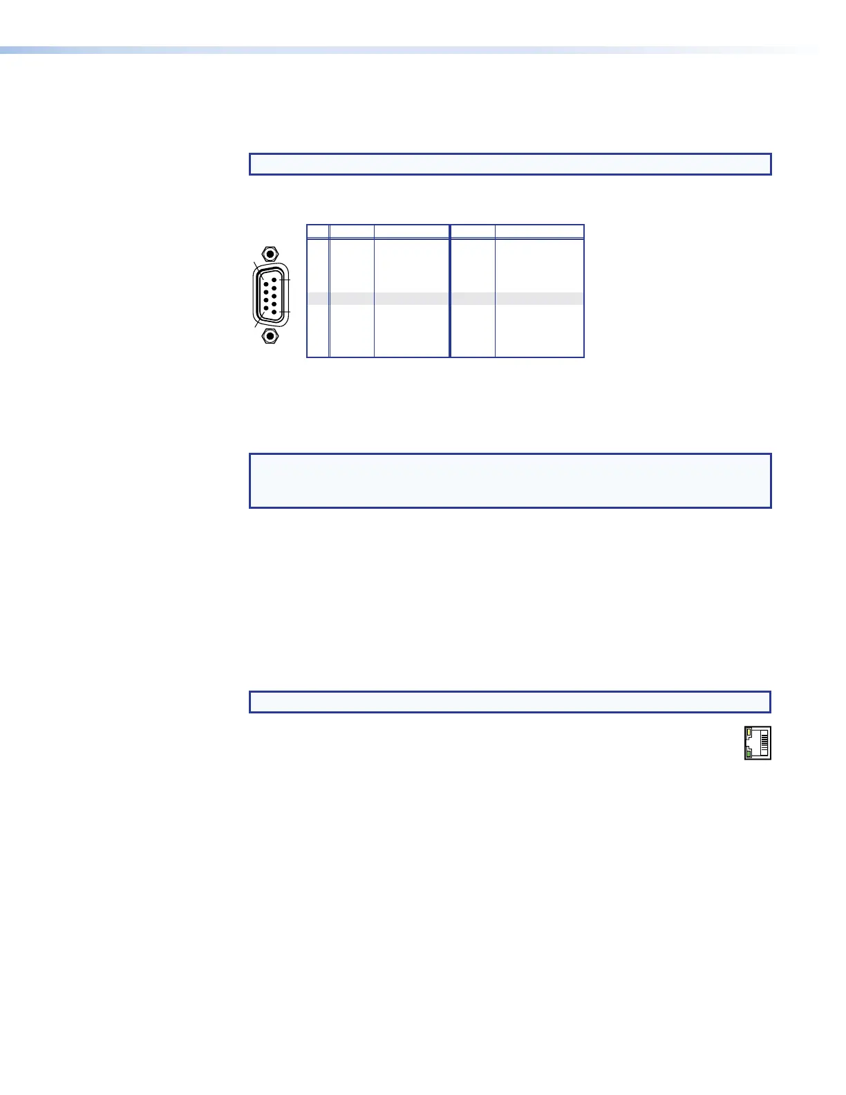
Remote Control Ports
C
Remote RS-232/RS-422 port —
NOTE: See figure 2 on page 11, figure 3 on page 12, and figure 5 on page 14.
Connect a host device, such as a computer or touchpanel control to the switcher via
this 9-pin D connector for serial RS-232/RS-422 control (see figure 28).
RS-232 FunctionPin Function
1
2
3
4
5
6
7
8
—
TX
RX
—
Gnd
—
—
—
Not used
Transmit data
Receive data
Not used
Signal ground
Not used
Not used
Not used
—
TX–
RX–
—
Gnd
—
RX+
TX+
Not used
Transmit data (–)
Receive data (–)
Not used
Signal ground
Not used
Receive data (+)
Transmit data (+)
1
5
Figure 28. Remote RS-232/RS-422 Port
See the Programming Guide section, beginning on page 76, for definitions of the SIS
commands (serial commands to control the switcher and connected endpoints via this
connector).
NOTE: The switcher can support either the RS-232 or RS-422 serial
communication protocol, and can operate at 9600, 19200, 38400, or 115200
baud rates.
See Selecting the Rear Panel Remote Port Protocol and Baud Rate on
page 64 to configure the RS-232/RS-422 port from the front panel.
If desired, connect an MKP 2000 or MKP 3000 remote control panel to the rear panel
Remote port on the switcher. Refer to the MKP 2000 Remote Control Panel User Guide
or the MKP 3000 User Guide for details.
Ethernet Connection
D
LAN port —
NOTE: See figure 2 on page 11, figure 3 on page 12, and figure 5 on page 14.
If desired, for IP control of the system, connect the matrix switcher to a PC or
N
ACT
LINK
to an Ethernet LAN via this RJ-45 connector. You can use a PC to control the
networked switcher with SIS commands from anywhere in the world. You can
also control the switcher from a PC that is running the Extron XTP
Configuration Software or has downloaded HTML pages from the switcher (see
TP connectors on page 21 to wire the connector).
Act LED indicator — Indicates transmission of data packets on the RJ-45 connector.
This LED should blink quickly as the switcher communicates.
Link LED indicator — Indicates that the switcher is properly connected to an Ethernet
LAN. This LED should light steadily.
XTP II CrossPoint 1600, 3200, and 6400 Switchers • Installation 27