version 4.7.2 – July 10th, 2022 Firmware version V2.1.7 and higher
EXXFIRE Installation and Service Manual 84
2. Service Mode (key cannot be removed in this position)
With the key in this position the system will have a number of additional functionalities
which are reserved for access level 2:
• The system can be reboot by simultaneously pressing buttons UP, DOWN and RESET
for a number of seconds.
• The system can be put in one of the DISABLED modes by pressing one of the supported
DISABLE button combinations; this will switch the DISABLED LED on; The DISABLED
mode can be ended by pressing the same DISABLE button combination again. See
section 7.6 for more information on the DISABLED mode.
• An Alarm can be reset by pressing the RESET ALARM/GAS RELEASED button. See
section 0 for more information on the RESET ALARM/GAS RELEASED operation.
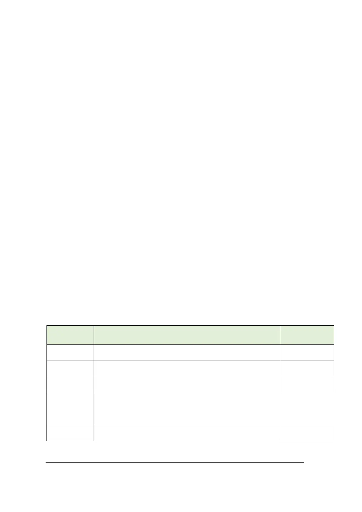
• Certain Fault conditions can be reset by pressing the RESET button under the 4-digit
fault code. The following faults (see Table 19) can be reset:
▪ Fault code 99 (flow fault 2); see section 0 for further information
▪ Fault code AA (flow fault 3); see section 0 for further information
▪ Fault code FF (service interval fault); see section 7.13 for further
information
• A new Commissioning cycle can be started by keeping button RESET ALARM/GAS
RELEASED pressed for some seconds during system start-up (see section 6)
• The service interval for the system can be set to one year from now by pressing the
DISABLE button for some seconds during system start-up (see section 7.13)
• Communication through the USB-B connector on the main board is enabled (access
level 3 only). Special software is required to interface to the system via this USB
connector.
On the UI panel 10 LEDS are used to indicate the overall system status and a 4-digit alphanumeric
display is used to show detailed fault information. A number of push buttons is available to control
the system. The functions of the LEDs and push buttons are described in the following table.