FSG 90 System
4 Functional Description
36 FAV_D10024 December 2014
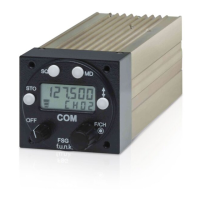
STO button has been pushed (same function at 5-digit display).
Upper line: Channel name (6-digits) to be stored
Lower line: Free channel memory number 07 (CH is flashing)
After pushing the STO button once more the channel name 121.875
(= 121.875 MHz) will be stored in the channel memory 07.
The last used Operating mode is displayed.
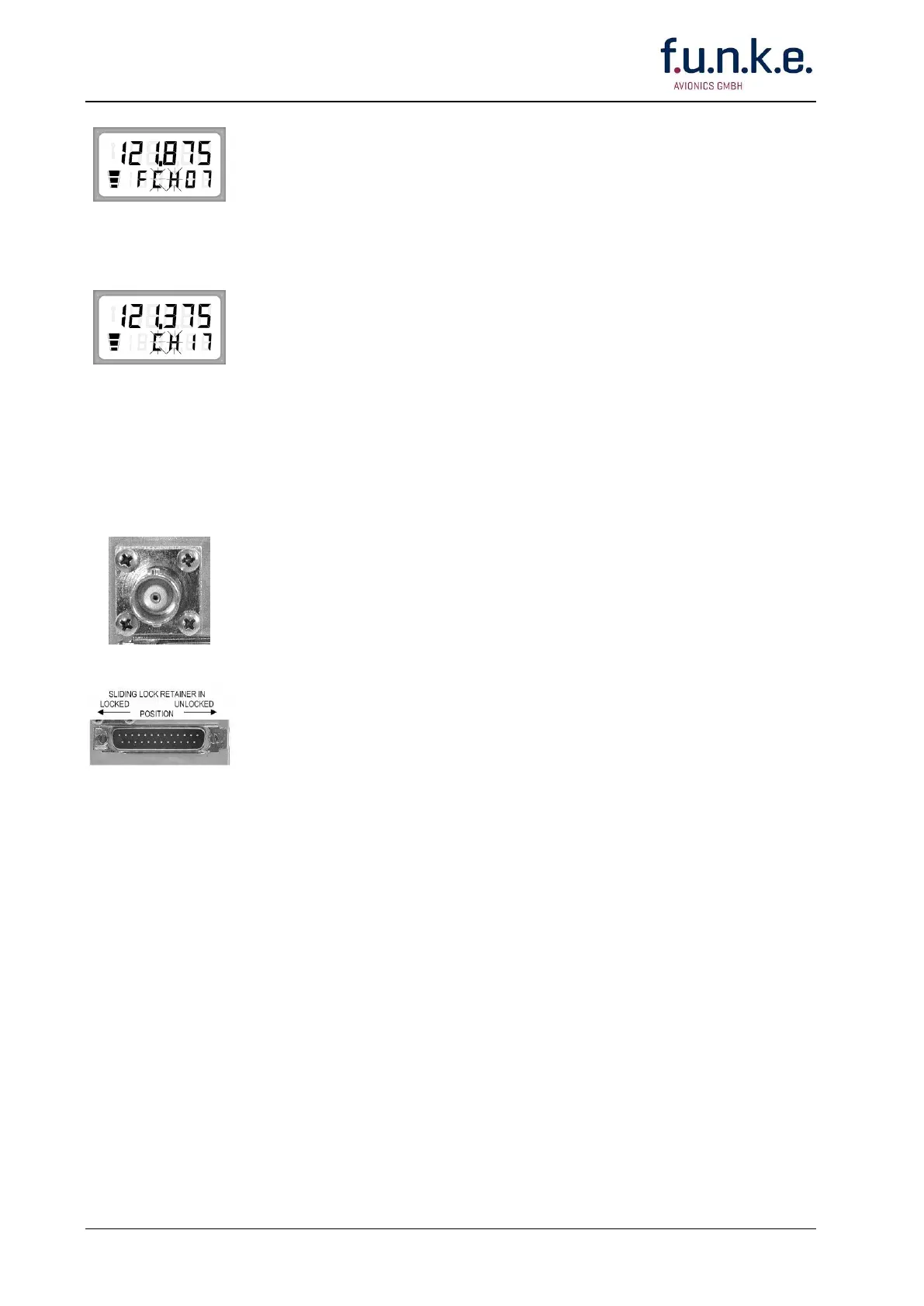
STO button has been pushed (same function at 5-digit display).
Upper line: Channel name (6-digits) to be stored
Lower line: Channel memory number 17 (CH is flashing)
After pushing the STO button once more the channel name 121.375
(= 121.375 MHz) will be stored in the channel memory 17. A previously
stored channel name will be overwritten.
The last used Operating mode is displayed.
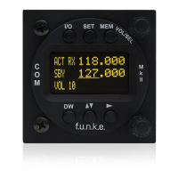
4.4 Connectors at the rear side
50 Ω BNC jack,
mating plug: BNC plug, UG 88/CU
Connects a suitable COM broad-band antenna with a frequency range of
at least 118 - 137 MHz.
Refer to section 3.4.3 for Installation.
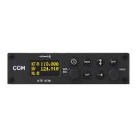
25-pole D-SUB receptacle, male, with sliding lock retainer
mating plug: 25-pole D-SUB, female, DA-25S, (A/N F10212: solder type,
including shell and mounting hardware),
to connect the aircraft wiring. Refer to section 3.5 for wiring.