8
400 12 732871 - Rev. D
1
2
3
4
5
8
9
8
3 45
76
Translation of the original instructions
ENGLISH
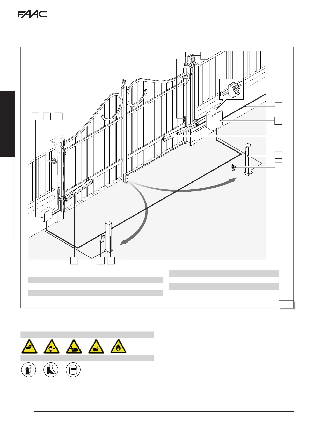
4.3 EXAMPLE SYSTEM
The example is purely an illustration and is only one of the possible applications of the 400.
1 Mains power supply 3G 1.5 sq. mm
2 Board enclosure and circuit breakers and differential switch
3 400 actuators 4G 1.5 sq. mm
4 Pair of internal photocells
5 Mechanical stops
6 Junction box
7 Key button
8 Pair of external photocells
9 Flashing light
5. INSTALLATION
RISKS
PERSONAL PROTECTIVE EQUIPMENT
!
The installation must comply with standard EN 12453. Mark off the work site and prohibit access/transit.
Installation must be carried out when it is not raining. If it is raining, adequate shelter for the actuator and the automation components must be provided until
installation is complete.