5
4
400 9 732871 - Rev. D
A
B
C
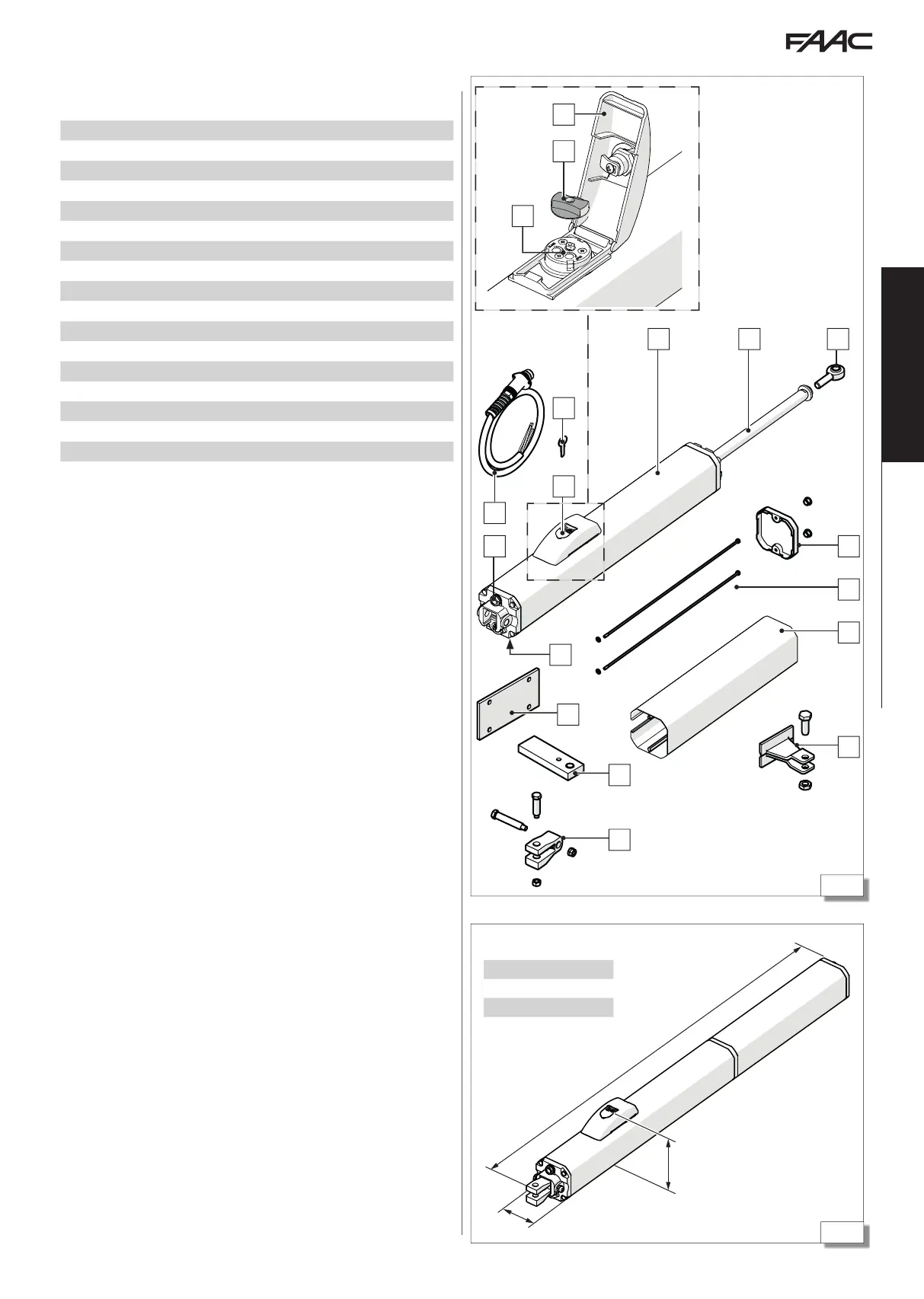
400 400 L
A 1020 1265
B 120 120
C 86 86
12
2
13
1
3
14
5
6
8
10
9
4
11
7
15
18
17
16
Translation of the original instructions
ENGLISH
3.7 COMPONENT IDENTIFICATION
COMPONENTS SUPPLIED
1 Actuator body
2 Rod
3 Joint
4 Casing cover with plugs
5 Casing fastening tie-rods with washers
6 Casing
7 Front bracket with fixing pin and nut
8 Rear fork with fixing pins and nuts
9 Rear bracket arm
10 Rear bracket plate
11 Breather screw
12 Oil filler plug
13 Power cable
14 Lock cover
15 Release key
16 Release device cover
17 Release knob
18 By-pass screws (force adjustment)
3.8 DIMENSIONS
The dimensions are indicated in figure (4).