31
30
400 25 732871 - Rev. D
S=0
B
70 80 90 100 110 120 130 140 150 160
A
80
105°
(1-2)
110°
(1-2)
115°
(1-2)
120°
(1-2)
125°
(1-2)
125°
(1-2)
115°
(1)
105°
(1)
100°
(1)
95°
(1)
90
105°
(2)
110°
(2)
115°
(2)
115°
(2)
120°
(2)
120° 110° 100° 95°
100
105°
(2)
105°
(2)
110°
(2)
115°
(2)
120°
(2)
110° 105° 95°
110
100°
(2)
105°
(2)
110°
(2)
115°
(2)
120°
(2)
105°
120
100°
(2)
105°
(2)
110°
(2)
110°
(2)
130
100°
(2)
S=40
B
90 100 110 120 130
A
120 90° 95° 100° 100° 95°
130 90° 95° 100° 95° 90°
140
90° 95° 95° 90°
150
90° 95° 90°
160 90° 90°
S=20
B
70 80 90 100 110 120 130 140 150
A
100
90°
(1)
95°
(1)
100°
(1)
105°
(1)
110°
(1)
110°
(1)
105°
(1)
95°
(1)
90°
(1)
110
90° 95° 100° 105° 110° 105° 100° 90°
120
90° 95° 100° 105° 110° 100° 95°
130
90° 95° 100° 105° 100° 95° 90°
140 90° 95° 100° 105° 95° 90°
150 90° 95°
A
B
D
Z
S
Y
5 mm
Translation of the original instructions
ENGLISH
2
Outward opening applications
11Outward opening - Measurements 400
(1) a closing electric lock has to be installed
(2) the speed of the leaf could be uneven during the final stage of movement
- during start-up and when not powered, invert the phase wires of
the motor to change the direction of travel.
- when adjusting the force (§ Adjusting the force - By-Pass), the
function of the by-pass screws is reversed: OPEN = regulates the
force during closing, CLOSE = regulates the force during opening.
For applications in which the gate opens outwards, a CBA has to be installed
to obtain the closing lock and a CBC to obtain an opening lock.
Refer to the following tables to establish the correct rear bracket
position. The maximum opening angle of the leaf is indicated in
the tables.
If necessary, modify the length and shape of the rear bracket arm
and then install it:
- A and B rear bracket installation measurements
- D distance between the edge of the pillar and the axis of the leaf
hinge
- Z distance between the fulcrum of the rear bracket and the pillar
- S distance between the axis of the leaf hinge and the mounting
surface of the front bracket
- Y distance between the fulcrum of the front bracket and the
surface of the leaf. According to the model:
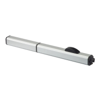
400 Y = 75 mm
400L Y = 100 mm
Install the actuator following the instructions in the specific sections
with the following differences:
- when fixing the front bracket, the rod should be fully retracted
and then pushed out by 5 mm (30).

 Loading...