10
9
400 13 732871 - Rev. D
2
3
1
A
D
Z
B
S
Y
S=0
B
80 90 100 110 120 130 140 150
A
80 110°
(1-2)
115°
(1-2)
120°
(1-2)
120°
(1-2)
125°
(1-2)
115°
(1)
105°
(1)
100°
(1)
90 105°
(1-2)
110°
(1-2)
115°
(1-2)
120°
(1-2)
120°
(1-2)
110°
(1)
100°
(1)
95°
(1)
100 105°
(2)
110°
(2)
115°
(2)
120°
(2)
110° 105° 95°
110 105°
(2)
110°
(2)
115°
(2)
115°
(2)
105° 100° 95°
120 105°
(2)
105°
(2)
110°
(2)
105° 100° 95°
130 100°
(2)
105°
(2)
110°
(2)
100° 95° 90°
140 100°
(2)
105°
(2)
100° 95° 90°
150 100°
(2)
100° 90° 85° 85°
160 100°
(2)
90° 85°
S=40
B
100 110 120 130 140 150
A
120
100°
(1)
95°
(1)
90°
(1)
85°
(1)
130
95°
(1)
90°
(1)
85°
(1)
140
95° 90° 85°
150
90° 85°
160
85° 85°
S=20
B
80 90 100 110 120 130 140 150
A
100
95°
(1)
100°
(1)
105°
(1)
110°
(1)
110°
(1)
105°
(1)
95°
(1)
95°
(1)
110
95°
(1)
100°
(1)
105°
(1)
110°
(1)
105°
(1)
100°
(1)
95°
(1)
95°
(1)
120
95° 100° 100° 105° 100° 95° 90°
130
95° 95° 100° 100° 95° 90° 85°
140
95° 100° 100° 95° 90° 86°
150
95° 95° 95° 85° 85°
160
95° 95° 85°
1 A - 50 mm
2 200 mm
3 B + 100 mm
Translation of the original instructions
ENGLISH
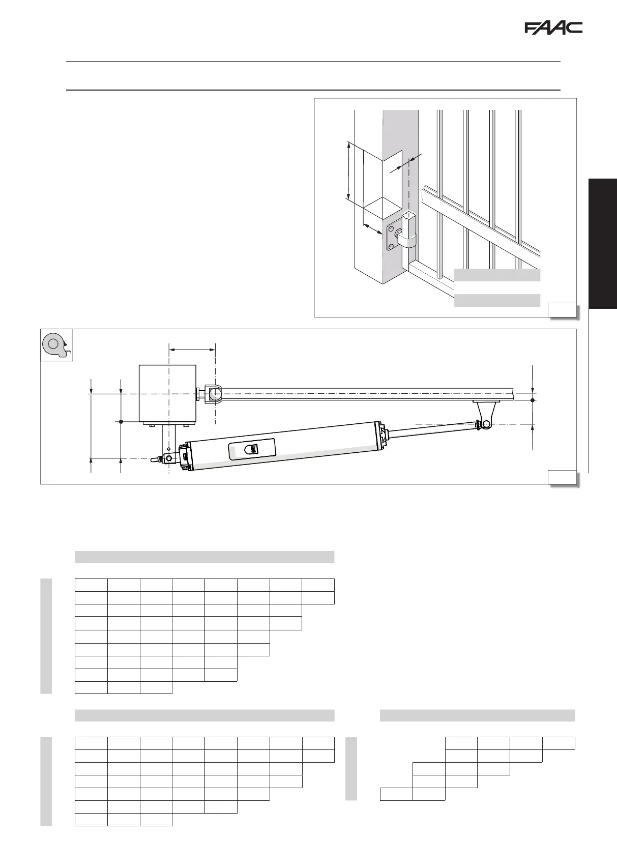
5.1 DETERMINING THE POSITION OF THE REAR BRACKET
The actuator must be installed inside the property, with the gate opening inwards.
For applications in which the gate opens outwards, see appendix.
2 Measurements 400
(1) a closing electric lock has to be installed
(2) the speed of the leaf could be uneven during the final stage of movement
Refer to the following tables to establish the correct position for the
rear bracket and then install it:
- A and B rear bracket installation measurements
- D distance between the edge of the pillar and the axis of the hinge
of the leaf. If the distance D does not allow the correct distance A
to be obtained, make a recess on the pillar (dimensions indicated
in the figure).
- Z distance between the fulcrum and the rear bracket (minimum =
50 mm to prevent the actuator touching the pillar). If necessary,
modify the length of the rear bracket arm.
- S the distance between the axis of the hinge of the leaf and the
mounting surface of the front bracket.
- Y distance between the fulcrum of the front bracket and the
surface of the leaf. According to the model:
400 Y = 75 mm
400L Y = 100 mm
The maximum opening angle of the leaf is indicated in the tables.