Installation manual
CNC 8035
5.
CONCEPTS
Movement with an electronic handwheel
(SOFT M: V15.3X)
(S
OFT T: V16.3X)
·190·
5.3 Movement with an electronic handwheel
Depending on their configuration, the available handwheels are:
• General handwheel.
It can be used to jog any axis one by one.
Select the axis and turn the handwheel to move it.
• Individual handwheel.
It replaces the mechanical handwheels.
Up to 2 handwheels can be used (one per axis).
It only moves the axis it is associated with.
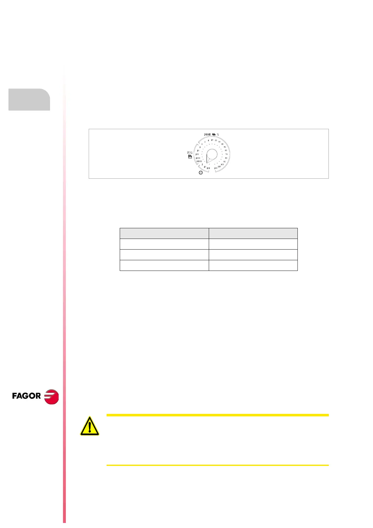
To move any of them, turn the switch to any of the handwheel positions. Positions 1, 10 and 100
indicate the multiplying factor being applied besides the internal x4 to the feedback pulses supplied
by the electronic handwheel.
For example, if the manufacturer has set a distance of 0.100 mm or 0.0100 inches per handwheel
turn for switch position 1:
There are 3 operating modes with handwheels:
Standard handwheel:
• With the general handwheel, select the axis to be moved and turn the handwheel.
• With individual handwheels, turn the handwheel associated with the axis to be moved.
Path handwheel
• For chamfering and rounding corners.
• 2 axes are moved along a selected path (chamfer or rounding) by moving a single handwheel.
• This feature must be managed from the PLC.
• The general handwheel is assumed as the "path handwheel" or the individual handwheel
associated with the X axis (Mill) or Z (lathe).
Feed handwheel mode
• To control the feedrate of the machine.
• This feature must be managed from the PLC.
Switch position Distance per turn
1 0.100 mm or 0.0100 inches
10 1.000 mm or 0.1000 inches
100 10.000 mm or 1.0000 inches
Depending on the turning speed of the handwheel and the position of the selector
switch, when requesting a movement at a faster feedrate than the maximum allowed.
• With individual handwheels, the movement stops when stopping the handwheel.
It does not move the indicated distance.
• With general handwheels, g.m.p. HDIFFBAC (P129) indicates whether the
movement is stopped or it moves the indicated distance.