Remote modules
CNC 8060
CNC 8065
5.
(REF: 1402)
·99·
RIOW REMOTE MODULES. (CANOPEN PROTOCOL).
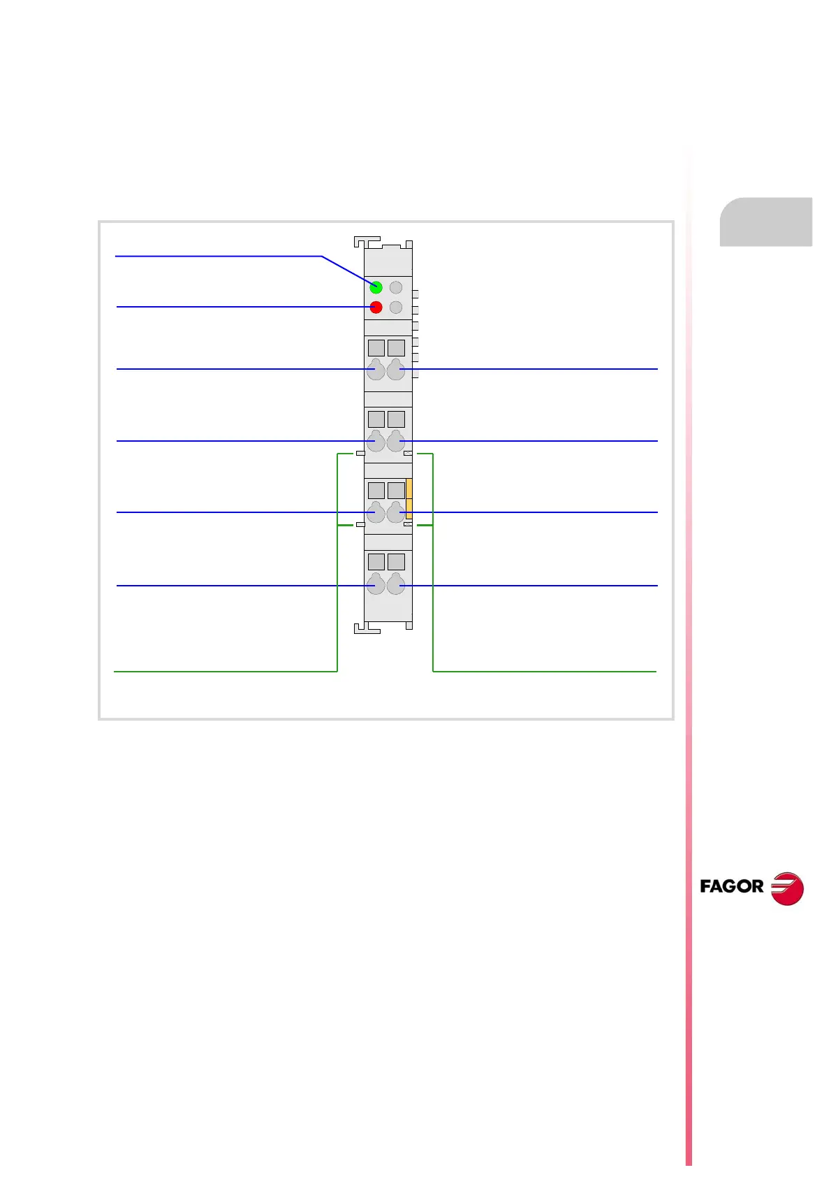
5.11 RIOW-4AO module. Module of 4 analog outputs.
Expansion module with four ±10 V DC analog outputs. The module has an LED indicating
the status of the bus an LED indicating an error at any of the outputs.
The 24 V DC needed to power the module comes from the previous module (inputs, outputs
module or power supply module) through the side power supplying jumpers). Likewise, this
module can also power the next module through the same jumpers. This module, by itself,
does not generate any voltage; it just receives the voltage generated by the previous RIOW-
PS24 module and passes it on to the next module.
Ground connection.
Analog output ·3·.
Ground connection.
Analog output ·1·.
Ground connection.
Analog output ·4·.
Ground connection.
Analog output ·2·.
Jumpers to power the next module.Jumpers to power the module.
Bus status indicator LED.
LED indicating an error at any
analog output.

 Loading...


