4-Channel Digital Video Recorder
25
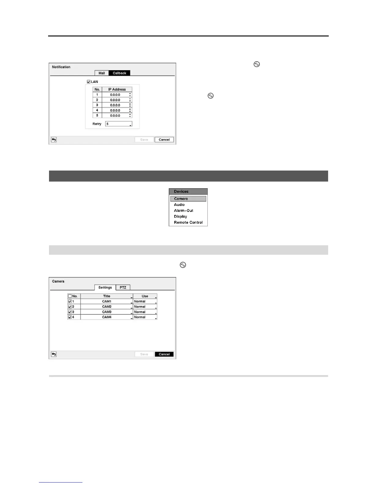
Highlight the Callback tab, and the Callback setup screen displays.
Devices Setup
Figure 28 ─ Devices menu.
Camera
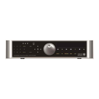
Highlight Camera in the Devices menu and press the button. The Camera setup screen appears.
Highlight the PTZ tab, and the PTZ setup screen displays.
Figure 27 ─ Notification Callback setup screen.
Highlight LAN and press the
button to toggle between On
and Off. When LAN is turned On you can change the IP
addresses.
Highlight the IP Address box that you want to change and
press the
button. Use the arrow buttons to enter the IP
address of the computer you want contacted during an event.
You can enter up to five IP addresses.
Highlight the box beside Retry and enter the number of times
you would like the DVR to try contacting the computer. You
can select from 1 to 10 retries.
Figure 29 ─ Camera setup screen.
You can turn the camera number On or Off, and you can
change the Title of each camera using the virtual keyboard.
You can also determine which cameras will display on the
monitors by selecting Normal, Covert 1 or Covert 2 from
a drop-down list in the Use column.
NOTE: When selecting the Covert 1, the DVR displays the
camera title and status icons on the covert video. When
selecting the Covert 2, the DVR displays only camera title
on the covert video.
NOTE: A user who does not have Covert Camera View
authority cannot view video from cameras set to Covert 1
or Covert 2 in both the live monitoring and playback modes.