AXLES, TIRES, and TRACKS Liquid Fertilizer Applicator A10 / A13 / A18 / A24 Page 46
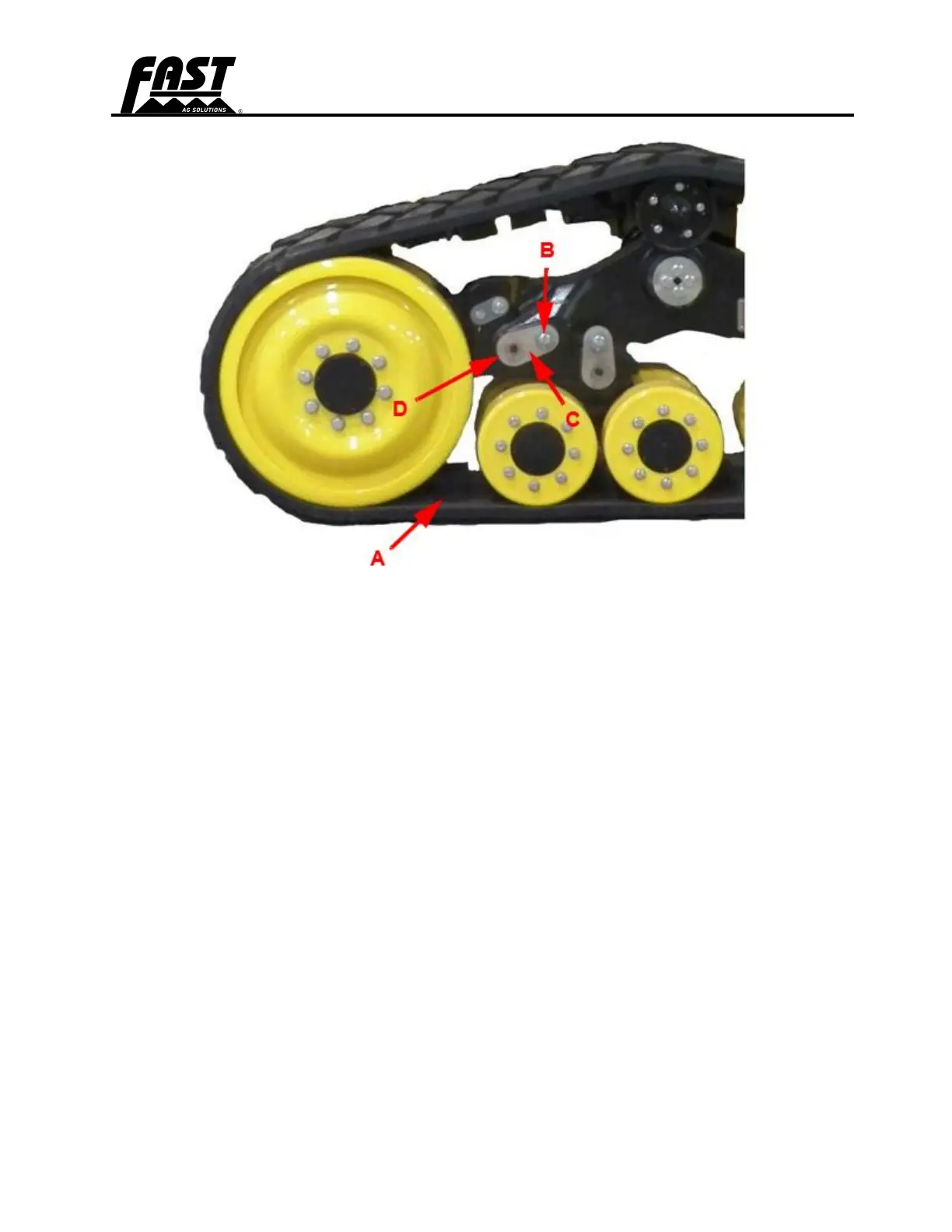
Track Alignment Procedure
1. Remove the alignment bolt retainer lock plate cap screws (B) and lock plate (C) from the
inboard and outboard sides of the undercarriage needing adjustment.
2. Loosen cap screw (D) counterclockwise 1.0-1.5 turns on the side of the undercarriage you
want the track to move towards (A represents location between inner idler wheel surface
and guide lug).
3. Tighten the special cap screw on the opposite side of the same undercarriage to 300 N-m
(221 ft-lbs.). Tighten cap screw loosened in Step 2 to the same specification.
a. A single full turn is the standard increment during adjustment. Lessen this amount
as final adjustment is approached.
4. Re-check track alignment and adjust until suitable clearance is obtained on both sides of
the guide lugs.
a. Lock plates are reversible for double the index increments.
b. If needed, increase torque on the special cap screw slightly allowing advancement
to a suitable lock plate position.
5. When alignment is complete, reinstall the lock plates and tighten cap screws to their
required torque specification of 130 N-m (95 ft-lbs.).