TRANSPORTING Liquid Fertilizer Applicator A10 / A13 / A18 / A24 Page 55
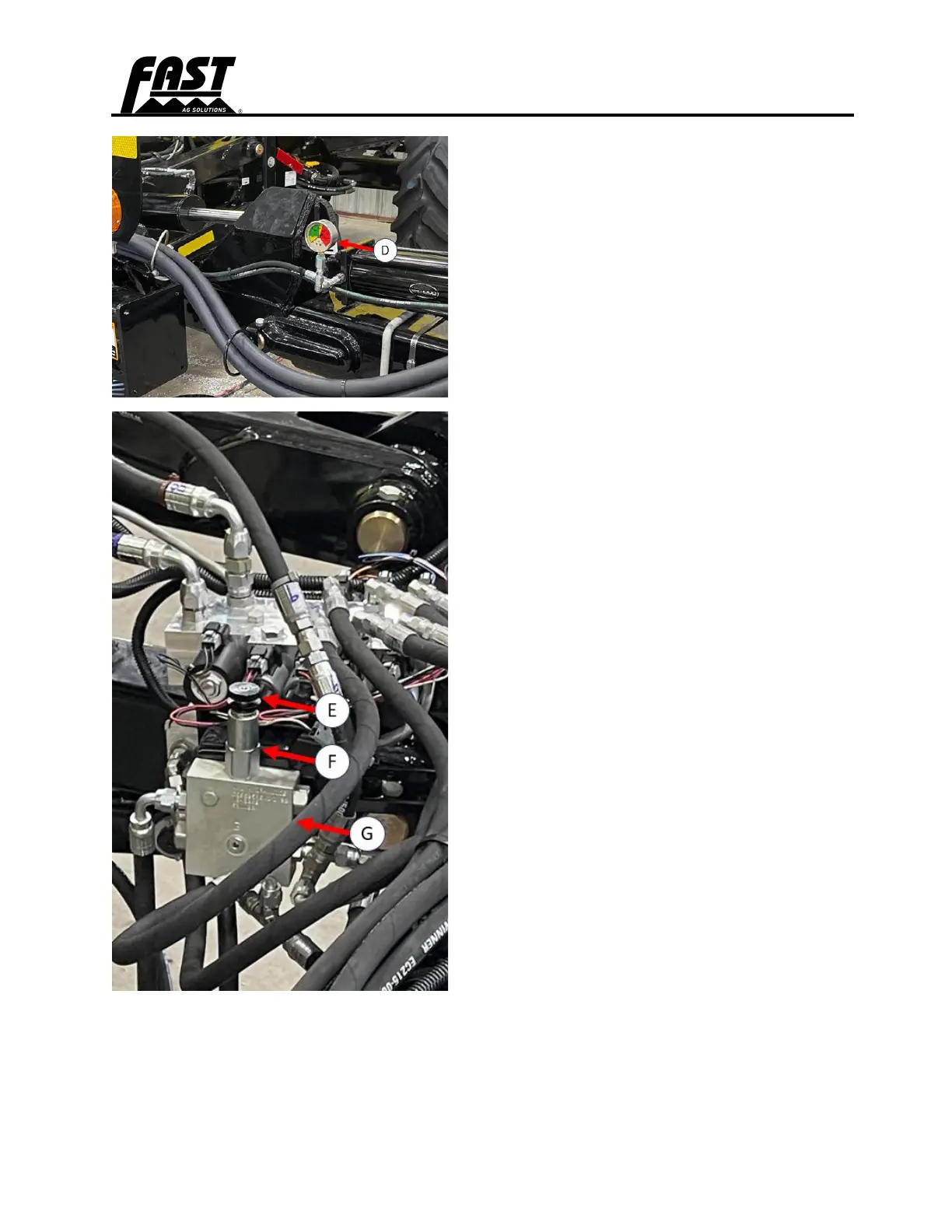
D. Gauge
E. Knob
F. Lock Ring
G. Down Pressure Valve
Unfolding/Extending the Toolbar
(continued)
7. Move flip wing switch (C) to Field
Position and hold to unfold flip wings
(if equipped.)
8. Keep switches (B) & (C) engaged to
maintain down pressure on the
wings.
9. Check the amount of down pressure
to inner wings by lowering the row
units to the ground while sitting still
and setting SCV I to continuous
down.
a. Hydraulic down pressure
gauge (D) should read
between 700 and 1000 psi but
see Step 10 below.
b. Down pressure may be
adjusted by turning knob (E)
on down pressure valve (G)
but see Step 10 below.
10. Use only as much down pressure as
needed to maintain a level toolbar
and consistent coulter or disc
penetration depth across the entire
toolbar. Excess pressure could cause
damage to the toolbar.
a. Turn knob clockwise to
increase pressure and
counterclockwise to decrease
down pressure.
b. To change pressure, loosen
lock ring (F) and turn
adjustment knob a 1/4 turn at
a time.
c. Do not exceed 1500 PSI.
11. Pull SCV I backward to fully raise
toolbar and kick wings up.
12. Toolbar is now ready for field
application.