Manual MWD BP
FEIG ELECTRONIC GmbH Page 31 of 97 MWD BP_Handbuch_mehrsprachig_8.doc
E N G L I S H
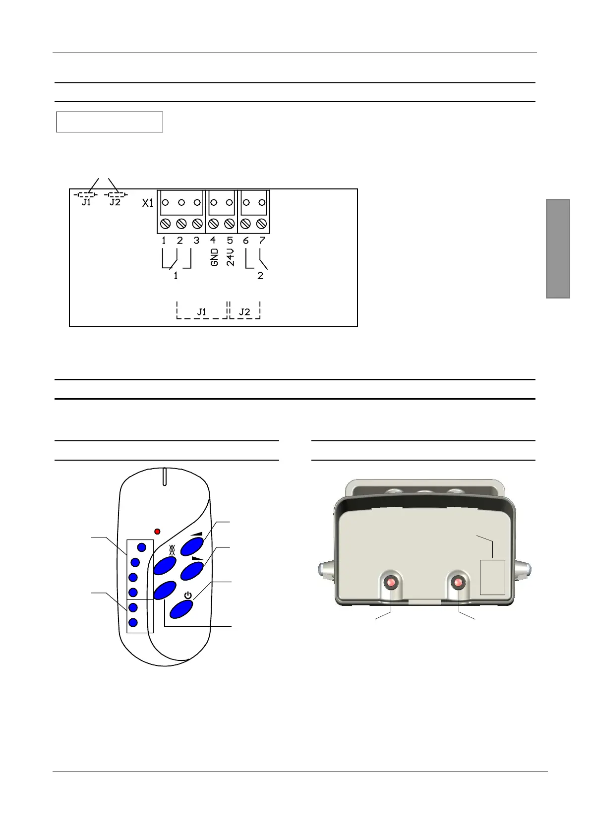
5.6 Electrical connection
IMPORTANT
The pins must be plugged as shown in the illustration below. A twisted or offset connection can
result in damage to the device.
On the back of the PCB
Fig. 5: Connection terminal on the rear side of the circuit board
)
The Common of the
relays (Terminal 2 and 7) is
connected directly to 24 V by
the Jumpers J1 and J2 with
some sensor versions, e.g.
version -A.
)
In order to cut the
Jumpers and thus the 24 V
connection, you have to cut
the 0
Ω
-resistors on the back
side of the PCB.
6 Operation of the motion detector …
The MWD BP Radar Motion Detector can be adjusted using the buttons on the case or using an optionally
available remote control.
6.1 ... with remote control
Volume +
Volume -
ON/OFF
Number
block
F-
buttons
i-button
MWD RC
1
2
3
4
F+
F-
i
Fig. 6: Remote control
6.2 ... with buttons on the case
Left button Right button
8
7-Segment
Display
Fig. 7: Operation using buttons


 To Next Page