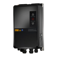
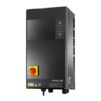
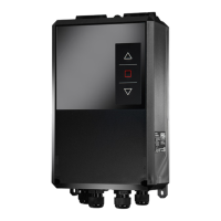
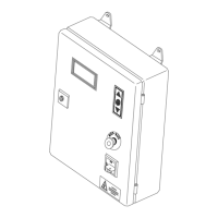
TST Startup FU3E
FEIG ELECTRONIC GmbH Page 10 of 29 FU3E_Inbetriebnahme_7_GB.doc
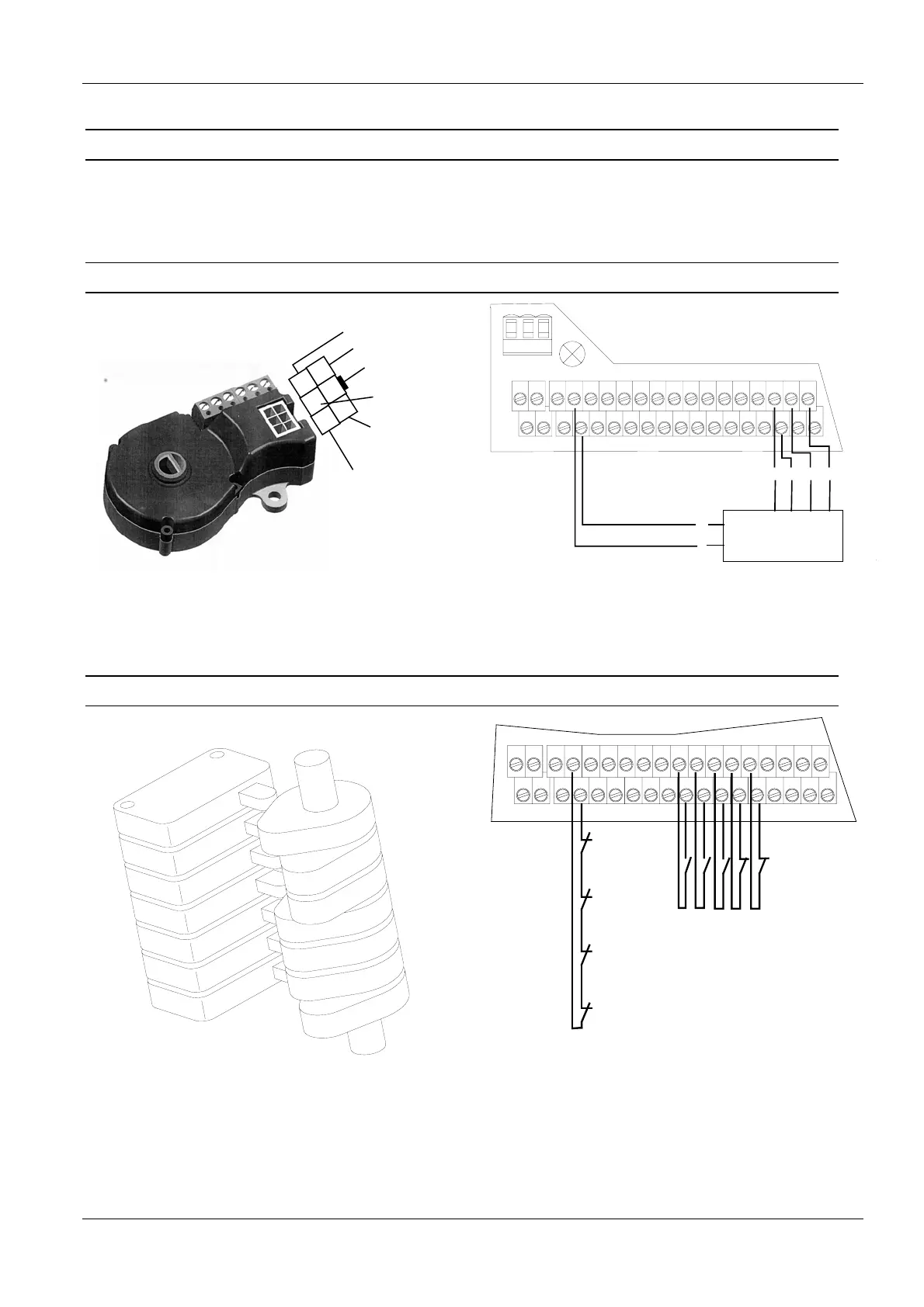
4.4 Connecting limit switches
Three various limit switch systems can be used with the TST FU3E door controller.
In the standard setting an absolute encoder is used as the limit switch. In addition, mechanical cam limit
switches or incremental encoders may be used.
4.4.1 Absolute encoder
4
5
6
1
2
3
GND
+12V
RS 485-B
RS 485-A
24V
emergency
stop line
emergency
stop line
Fig. 6: Absolute encoder
X13
X20
X14
Si2
12V
Si1
S1a S2a
S1b S2b
13
24
57
68
911
10 12
13 15
14 16
17 19
18 20
21 23
22 24
25 27
26 28
29 31
30 32
X18 X17
3
2
4
6
Absolute encoder
1
5
4236
1
5
12V
GND
B
A
Fig. 7: Connecting the absolute encoder
4.4.2 Mechanical limit switches
Fig. 8: Cam switch
Limit switch OPEN
Limit switch CLOSE
Pre limit switch OPEN
Pre limit switch CLOSE
Pre limit switch edge
Emergency
limit switch
CLOSE
Emergency
limit switch
OPEN
Crank switch
Thermo pill
X13X14
S1a S2a
S1b S2b
13
24
57
68
911
10 12
13 15
14 16
17 19
18 20
21 23
22 24
25 27
26 28
29 31
30 32
X18 X17
Fig. 9: Connecting cam switches
)Alternately the pre-limit switches can also be connected as normally closed contacts