TST Startup FU3E
FEIG ELECTRONIC GmbH Page 8 of 29 FU3E_Inbetriebnahme_7_GB.doc
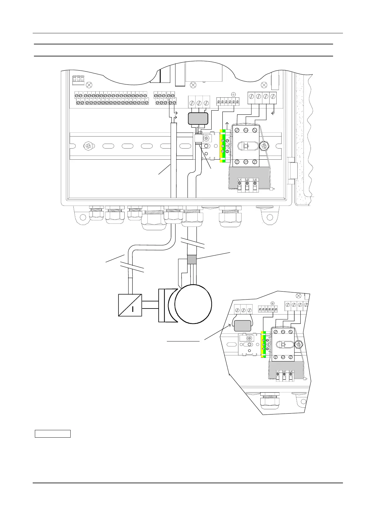
4.2 Motor connections
NPE
X13
X20
X14
Si212V
Si1
L1 L2 L3 L3´
S1a S2a
S1b S2b
13
24
57
68
911
10 12
13 15
14 16
17 19
18 20
21 23
22 24
25 27
26 28
29 31
30 32
41
42
43 45
44 46
51 54
53 53
T2
X4
T1
T3
PE
X1 L1
PE PE PE PE PE
L3'L2 L3
F204
2,5A-T
X16
X15
X17A
X18 X17
UV
W
PE
L3´
53
L
N
The shield of
motor cable
has to
connect with
PE-clamp
N
Connection sample:
Break in working
current principle
3~
M
W
V
U
P
E
B
r
eak
r
e
c
t
i
f
i
er
S
hi
el
d
of
m
ot
or
c
abl
e
~
. . .
~
~
C
on
t
r
ol
c
ab
l
e
i
nc
l
.
br
eak
c
onnec
t
i
on
an
d
end
s
w
i
t
c
h
c
onnec
t
i
on
+
-
NPE
L1 L2 L3 L3´
T2
X
4
T1
T3
X
2
P
E
X
1
L
1
P
E
P
E
P
E
P
E
P
E
L3
'
L
2
L
3
IMPORTANT
The wire bridge wich
is used as transport
lock for the ferrit core
must be removed
before connecting the
motor cable !
Fig. 4: Motor connections
MPORTANT
To ensure flawless function of the TST FU3E door controller, a shielded motor cable must be used. In
addition, no other wires may be routed except for those connecting the motor.
If a motor with electro mechanical break is used you have to observe that the break is noise-
suppressed. We recommend to suppress noise with RC-devices.