TST Startup FU3E
FEIG ELECTRONIC GmbH Page 9 of 29 FU3E_Inbetriebnahme_7_GB.doc
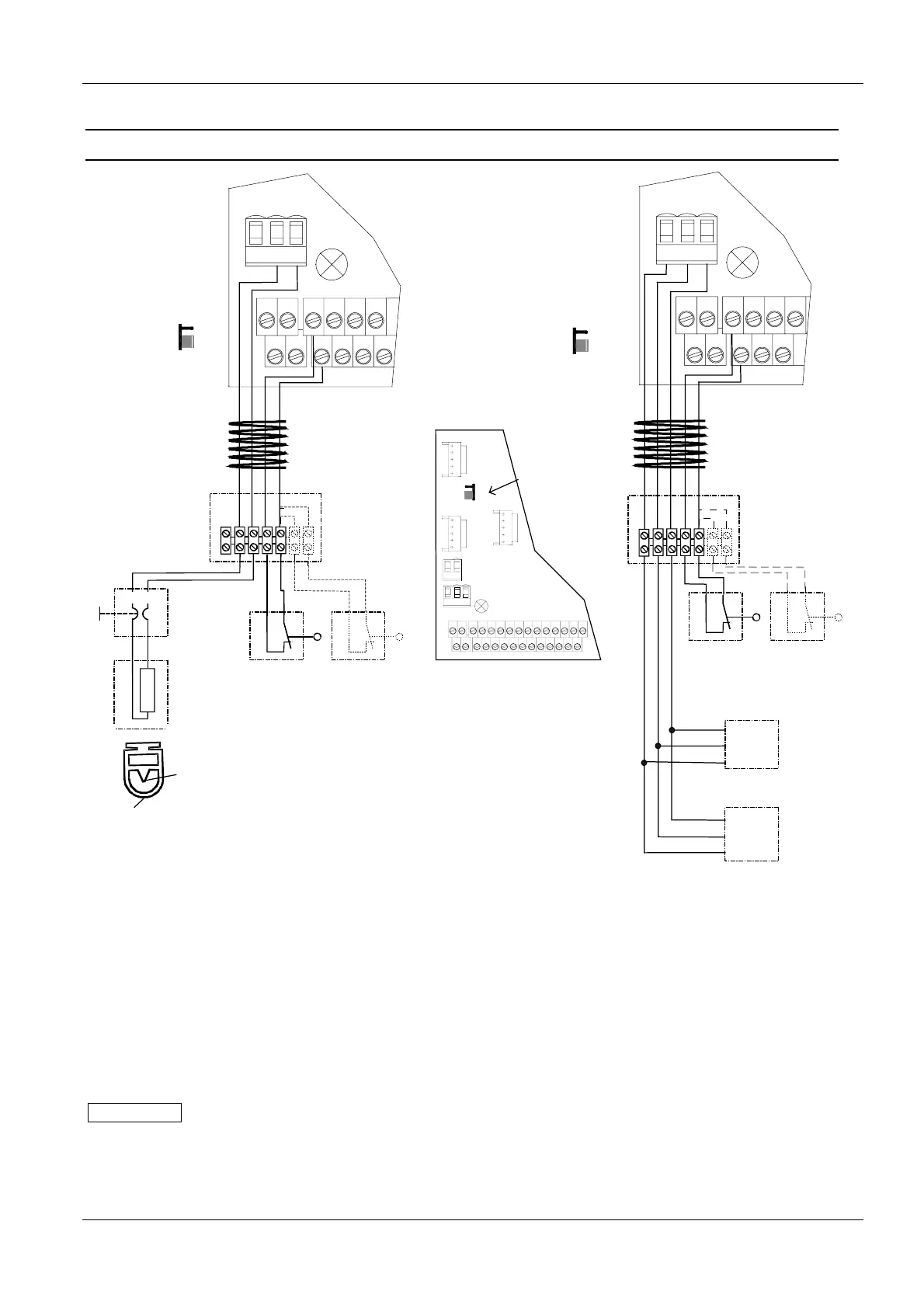
4.3 Connecting the safety edge
Spiral cable
"electricel" edge
J 600: 1 - 2
Dynamical optical
system
J 600: 1 - 2
3
Spiral cable
3
1
X13
X20
X14
Si2
12V
Si1
S1a S2a
S1b S2b
13
24
57
68
Junction
box
Slack rope
switch
8k2
Safety
edge
Terminal
resistor
Optional
slip door
brown
white
Outside
(white)
Inside
(brown)
1
2
Si2 Si1
Receiver
Trans-
mitter
Green
White
Brown
Junction
box
1
2
12V
Si2 Si1
X13
X20
X14
Si2
12V
Si1
S1a S2a
S1b S2b
13
24
57
68
1
The Jumper J 600
is placed at the left
border of the
board
J600
8,2K
1,2K
3
1
X20
X14 X13
X19
X807
X806
X802
X18
Si212V
Si1
Si3 Si4
S1a S2a
S1b S2b
13
24
57
68
911
10 12
13 15
14 16
17 19
18 20
21 23
22 24
25
Optional
slip door
Slack rope
switch
Fig. 5: Connecting the safety edge
Various types of safety edges can be connected, for example:
• Electrical safety edge with 1.2kΩ or 8.2kΩ terminating resistor.
• Dynamic optical systems.
If one of these safety edges is connected when the TST FU3E door controller is turned on, the edge is
automatically detected.
IMPORTANT
If no safety edge is connected, automatic closing of the door is not possible.
Use of other safety edge types is possible. Please contact the door manufacturer.