35
AD 951
212UBB
"!
&
#
$%
"
!
Planer-Thicknesser
A 941 / AD 941 / AD 951
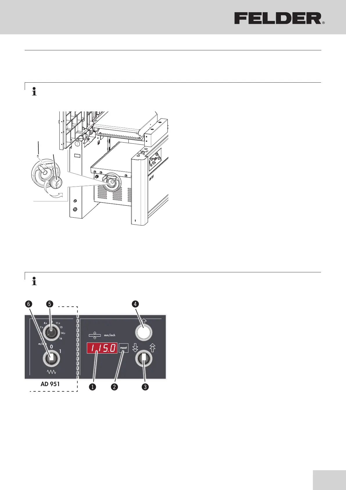
The digital indicators may lose their calibration
during transport. To set the indicator precisely,
open the clamping screw and remove from the
handwheel. Turn it until the mea-sured value of
a previously processed workpiece is precisely
displayed.
Reinsert the indicator into the handwheel and
carefully tighten the clamping screw.
!Digital clock
"Clamping screw
Digi-Drive or Power-Drive:
Procedure: see the following pages
Fig. 8-8: Standard equipment (with the handwheel)
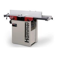
Set the thicknesser height:
• Setting the planer table height using key in steps of
0,1 mm / 0,005 “.
• To move, use the quick motion use switch.
Calibration of control unit:
• Move the thicknesser table to 20 mm/0,790 “
position (using a test piece).
• Press Reset key for 10 seconds.
Conversion mm/inch
• Press Reset key while switching on the machine
(main switch).
!Actual value display
"Reset button
#Quick motion switch
$Set the thicknesser height
%Potentiometer
&ON/OFF feeder switch
8.7 Height adjustment of the thicknesser table with the handwheel
Note:
To compensate for the thread clearance, adjust the thicknessing table from bottom to top.
Note:
To compensate for the thread clearance, adjust the thicknessing table from bottom to top.
8.8 “Power-Drive” equipment
Fig. 8-9: Power-Drive
Making adjustments and preparations