48
#
$
!
"
%
Planer-Thicknesser
A 941 / AD 941 / AD 951
1. Before beginning any maintenance work on the
machine, switch it off and secure it against acciden-
tally being switched on again.
2. If required, retool from surface planing to thickness
planing.
3. Extraction system must be connected.
4. Every time the machine is put into operation, test the
kickback guards to ensure that they are functioning
properly.
5. Adjust the thicknessing height.
6. Switch machine on.
AD 941
Raise or lower the gear lever:
• Position up: Feed 6 m/min
• Position down: Feed12 m/min.
AD 951
Select the feed speed with the potentiometer.
Start the motor and engage the gearbox with the
button.
Machining the workpiece:
Place the surface-planed side of the workpiece on
the thicknesser table and push into the machine until
it is drawn in by the feed rollers.
Infeed roller - standard:
A maximum of 2 workpieces can be planed to thickness
simultaneously. These must be pushed in at each end of
the feed roller.
Maximum offset from workpiece to workpiece 1 mm.
Infeed roller - rubber or segmented:
Several workpieces with differing thicknesses can be
machined.
The maximum difference between workpiece to
workpiece measures 1 mm.
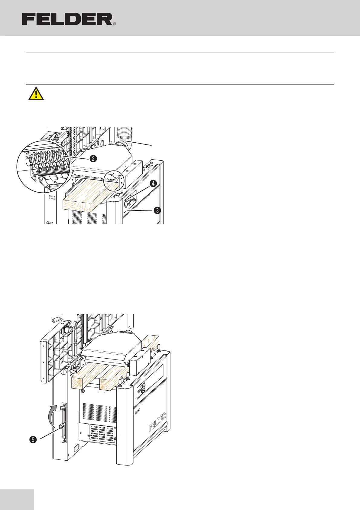
Fig. 9-10: Thickness planing
Fig. 9-9: Thickness planing
!Vacuum hose
"Kickback guards
#ON/OFF feeder switch
$Potentiometer
%Gear lever (AD 941)
9.5.2 Thickness planing
Operation
Warning! Risk of injury through accidental contact with the rota-ting cutterblock
Never reach into the infeed or outfeed side while the machine is running (during machining or idling)!