11
EN
Cod. 3540001190 - Rev. 00 - 11/2023
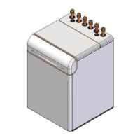
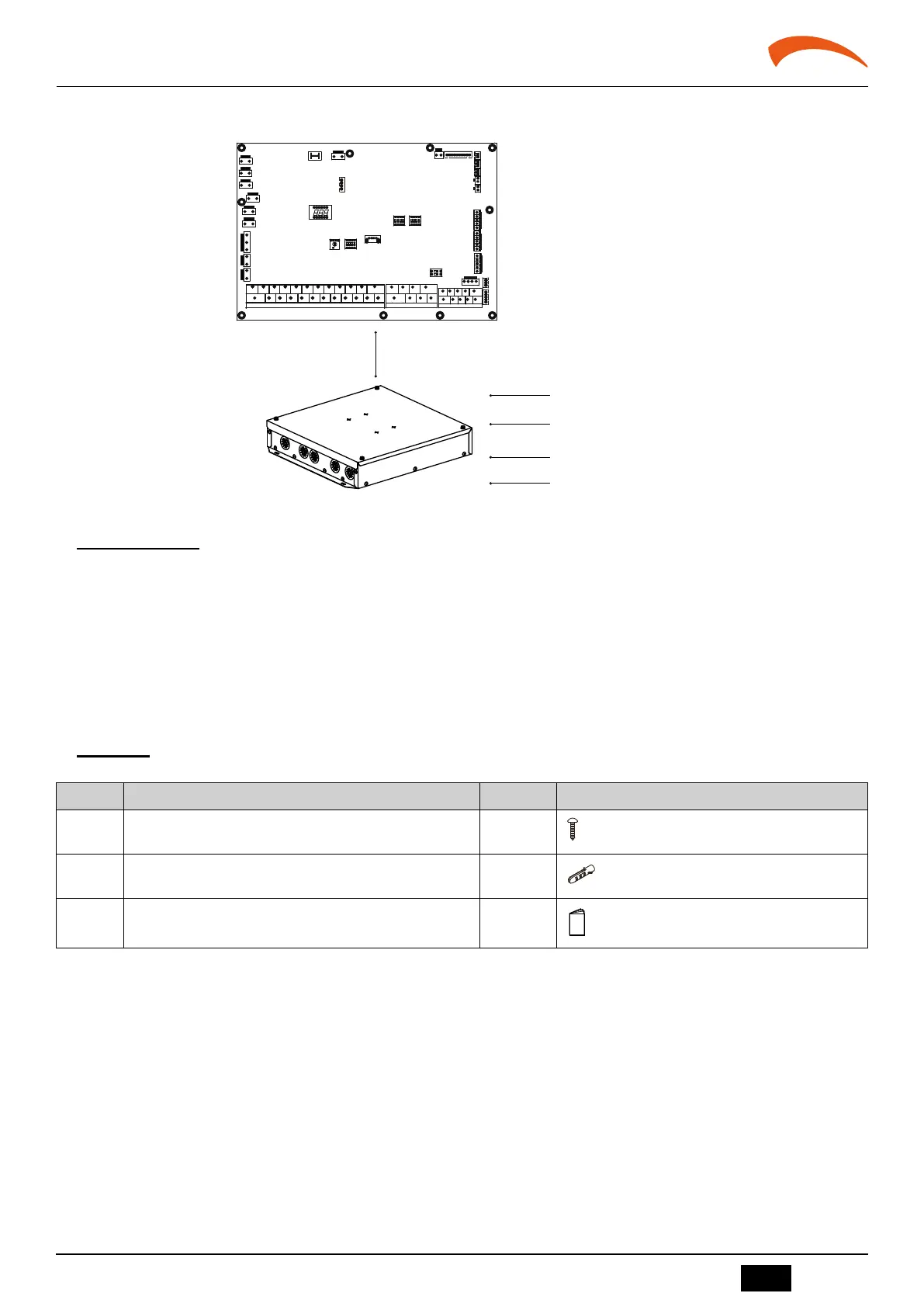
HYDRAULIC ELECTRONIC BOARD BOX
2. GENERAL INTRODUCTION
This kit is used to shorten the eld connection cable length between hydraulic module PCB and TBH, external electric heater, AHS, SV1, SV2, SV3,
PUMP_O, PUMP_D, PUMP_C, PUMP_S, P_X, making the installation more exible.
Communication cable ≤ 50m
TBH
External Backup heater
AHS
.........
3029
32
25 26 27 28
31
7
1211
109
18
8
7
5
1 2
22 23 2413
3
4
6
2014 15 17 1916 21
6 8 9
10
5
4321
CN4
CN22
CN5
S3
DIS1
CN24
CN1
CN2
CN8
CN6
CN13
CN15
CN16
CN18
CN28
S2
CN42
CN21
S1
S4
CN7CN11
CN17
CN14
CN19
CN30
CN35
CN31
CN36
CN25
CN29
CN40
CN41
CN32
SW9
External backup heater
Communication cable ≤50m
fig. 1 -
2.1 Function description
1. The hydraulic module board and external kit simultaneously output the open/close of port of TBH, IBH2, IBH1, AHS, SV1, SV2, SV3, PUMP_O, PUMP_D,
PUMP_C, PUMP_S, P_X.
2. The hydraulic module board and external kit are both tested for AD values of port T5, Tbt, T5_2, Tw2, T1, Tsolar. If neither the hydraulic module board nor the external
kit has collected the set active sensor parameters, the hydraulic module board reports a corresponding sensor fault.When the hydraulic module board and the external
kit simultaneously collect different parameter values of the same sensor, the hydraulic module board parameter values shall prevail.
3. Disconnect communication with the main control board for more than 1 minute, the hydraulic module will shut down and output an EL fault, and the fault display on
the wire controller.
4. Connection for other components see the “INSTALLATION AND OWNER’S MANUAL” of indoor unit.
3. INSTALLATION GUIDELINE
3.1 Accessories
The following accessories are included.
No. Description Qty. Remarks
1 Cross round head tapping screw 5
ST3.9*25 (4 for actual installation)
2 Plastic expansion pipe 5
Φ6X31.5mm (4 for actual installation)
3 Installation and owner’s manual(this book) 1
 Loading...