13
EN
Cod. 3540001190 - Rev. 00 - 11/2023
HYDRAULIC ELECTRONIC BOARD BOX
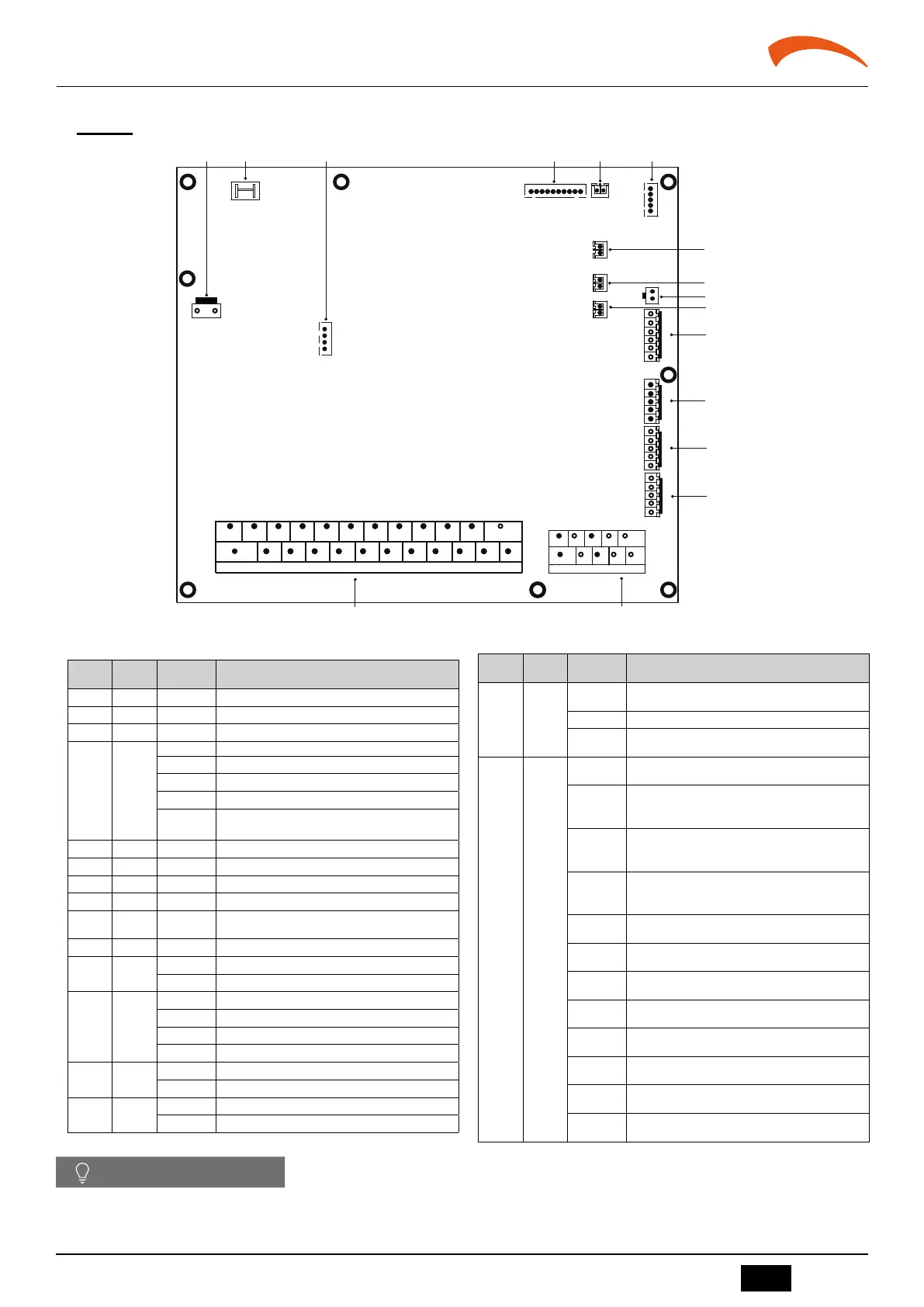
5. CONTROL BOARD
5.1 CB board
16
7
1211
109
18
8
7
5
1
22 23 24
2
13
3
4
6
2014 15 17 1916 21
6 8 9
10
21
CN5
CN15
CN18
CN21
CN11
CN30
2
CN25
CN6
CN24
CN36
CN35
CN31
CN66
CN23
1 3 4 5 6
8
9
11
12
13
14
15
CN38
10
CN13
7
E T1 T2 M2 M1 EVU SG
S2 S1 K2 K1
CL COM HT 0-10V
3
X/HA
5
E
4
Y/HB
fig. 4 -
Order Port Code Description
1 CN21 POWER Port for power supply
2 CN5 GND Port for ground
3 CN25 DEBUG Port for IC programming
4 CN6
T2 Reserved
T2B Reserved
TW_in Reserved
TW_out Reserved
T1
Port for temperature sensor of final outlet water tempe-
rature
5 CN24 Tbt Port for temperature sensor of balance tank
6 CN23 RH Port for humidity sensor (Reserved)
7 CN13 T5 Port for domestic hot water tank temp. sensor
8 CN15 Tw2 Port for outlet water for zone 2 temp. sensor
9 CN38 T52
Port for temperature sensor (Reserved)
10 CN18 Tsolar Port for solar panel temp sensor
11 CN66
K1 K2 Input port (Reserved)
S1 S2 Input port for solar energy
12 CN31
10V GND Reserved
HT Control port for room thermostat
COM Power port for room thermostat
CL Control port for room thermostat
13 CN35
SG Port for smart grid (grid signal)
EVU Port for smart grid (photovoltaic signal)
14 CN36
M1 M2 Port for remote switch
T1 T2 Reserved
Order Port Code Description
15 CN30
3 (X/HA)
4 (Y/HB)
Port for communication with hydraulic module board
6 (P) 7(Q) Reserved
9 (H1)
10 (H2)
Reserved
16 CN11
1 (AHS1)
2 (AHS2)
Port for additional heat source
3 (1ON)
4 (2OFF)
17 (C1)
Port for SV1(3-way valve)
5 (2ON)
6 (2OFF)
18 (C1)
Port for SV2(3-way valve)
7 (3ON)
8 (3OFF)
19 (C1)
Port for SV3(3-way valve)
9 (P_c)
20 (C1)
Port for zone 2 pump
10 (P_o)
21 (C1)
Port for outside circulation pump
11 (P_s)
22 (C1)
Port for solar energy pump
12 (P_d)
23 (C1)
Port for DHW pipe pump
13 (TBH)
16 (C1)
Control port for tank booster heater
14 (IBH2)
16 (C1)
Control port for internal backup heater 1
15 (IBH1)
17 (C1)
Control port for internal backup heater 2
24 (P_X)
23 (C1)
Output port for alarm/Defrost run
NOTE
If the Tbt and T5 terminals need to be connected, you can unplug the connecting wire from the corresponding position on the Hydraulic module board and
plug it into the kit PCB board port.
 Loading...