3 Commissioning as function module F24
Festo – P.BE-CPX-FB23-24-EN – 1305a – English 39
Configuration example
The following example describes a specific configuration of a CPX terminal with digital and analog I/O
modules and MPA pneumatics, and the resulting allocation of I/O data, depending on the selected
mapping optimisation.
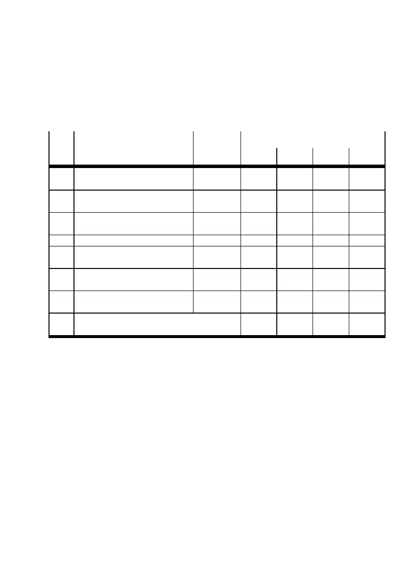
Configuration of the CPX terminal
Mo-
dule
no.
Electric modules Module
identifier
1)
Assigned addresses
RX RY RWr RWw
0 Bus node FB23-24 (F24)
with system diagnostics
FB24-RIO 2bytes
2)
2bytes
2)
2bytes
3)
(1 word)
2bytes
3)
(1 word)
1 Digital8-foldinputand8-fold
output module
8DI/8DO 1byte 1byte – –
2 Analogue 4-fold input module 4AI – – 8bytes
(4 words)
–
3 Digital 8-fold input module 8DI 1byte – – –
4 Analogue 2-fold output module 2AO – – – 4bytes
(2 words)
5 Analogue 4-fold input module 4AI – – 8bytes
(4 words)
–
6 MPA pneumatic module (type 32)
with electrical isolation
MPA1S – 1bytes – –
Sum of the respective address ranges 4bytes 4bytes 18 bytes
(9 words)
6bytes
(3 words)
1)
Module identifiers on the Festo Maintenance Tool (CPX-FMT) or handheld (CPX-MM I) for I/O mod-
ules these are shown in the inspection window of the module.
2)
Remote Ready bit always occupies the address space of 2 bytes in the bit range (RX, RY) at the end
of the last station with 1 bit.
3)
The system diagnostics (status bits and I/O diagnostic interface) oc cupies 16 I/Os (the first word)
in the word range of the first station (RWr, RWw).
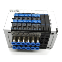
Tab. 3.2 Configuration example for the CPX terminal depicted in Fig. 3.3 andFig. 3.4




 To Next Page