3 Commissioning as function module F24
40 Festo – P.BE-CPX-FB23-24-EN – 1305a – English
Optimised cycle time assignment of I/O data
The following configuration arises from the address capacity of the CPX terminal:
3 stations, 1-fold cycle time.
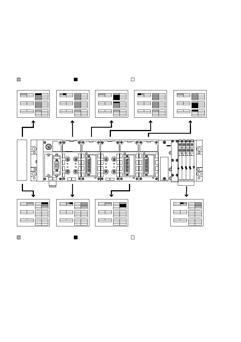
TheFigure( Fig. 3.3) shows the distribution of module-specific I/O data in the CC-Link specific ad-
dress ranges, and the arrangement and sequence of I/O data within these address ranges.
System diagnosis
Inputs (RX, RWr)
Outputs (RY, RWw)
2AO4AI 8DI
8DO
1
2
RX RY RWr RWw
4A
I
Remote ready
3
1
2
RX RY RWr RWw
Remote ready
3
8DI/8DO
1
2
RX RY RWr RWw
Remote ready
3
1
2
RX RY RWr RWw
Remote ready
3
1
2
RX RY RWr RWw
Remote ready
3
1
2
RX RY RWr RWw
Remote ready
3
1
2
RX RY RWr RWw
Rem ote ready
3
1
2
RX RY RWr RWw
Remote ready
3
D1000 D1005 … D1008
D2000 Y1008 ... Y100F
X1000 … X1007 D1001 … D1004 X1008 … X100F
D2001, D2002
1
2
RX RY RWr RWw
Remote ready
3
Y1000 ... Y1007
X1000, Y1000, D1000, D2000… Exemplary representation of the CC-Link address assignment
(hexadecimal)
Allocat ed address spac e
Allocat ed address spac e
Available address space
Available address space
Fig. 3.3 Optimised cycle time addressing of the CPX terminal desc ribed in theTab. 3.2




 To Next Page