5 Function module F23
72 Festo – P.BE-CPX-FB23-24-EN – 1305a – English
Analogue inputs and outpu ts
Digital I/Os occupy from the first station, if it is not assigned to system diagnostics or to digital I /Os,
one after the other the word range ( RWr/RWw) ( section 5.3.1).
Control bits for analogue outputs
Analogue output s additionally occupy in the bit range of the corresponding station respectively one
control bit.
The bit range of the stations used by the analogue outputs is reserved.
Analogue outputs can be activated or deactivated with the word “Control” in the bit range of the relev-
ant station ( Tab. 5.4). The following bits are used here:
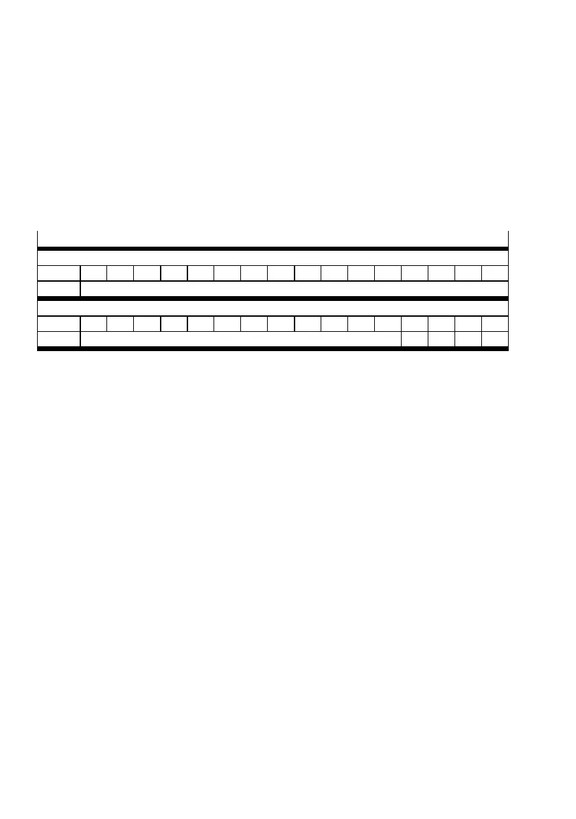
Control
Slave > Master – RX(n+m)
Bit: 15 14 13 12 11 10 9 8 7 6 5 4 3 2 1 0
Signal: Reserved
Master > Slave – RY(n+m)
Bit: 15 14 13 12 11 10 9 8 7 6 5 4 3 2 1 0
Signal: Reserved S3 S2 S1 S0
S…: Enable/Disable channel 0, 1, 2, 3 ( and/or 4, 5, 6, 7 or 8, 9, 10, 11 or 12, 13, 14, 15)
Control bit for the relevant analogue output. The relevant output is reset with a 0-signal.
n: assigned CC-Link slave address
m: 1. Station: m = 0
2. Station: m = 2
3. Station: m = 4
4. Station: m = 6
Tab. 5.4 Control
 Loading...


