5 Function module F23
Festo – P.BE-CPX-FB23-24-EN – 1305a – English 73
System diagnosis
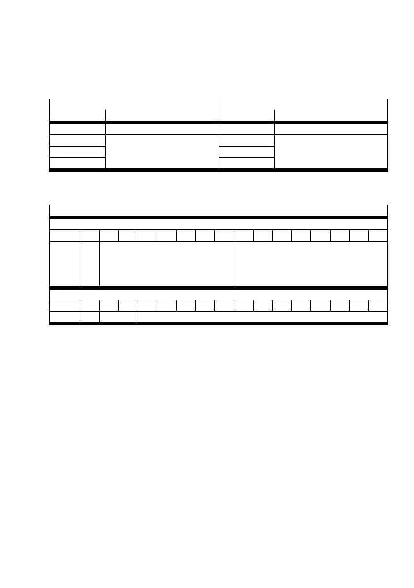
The following tables show the assignment of the word range of the first station of the CPX terminal with
activated system diagnostics.
Slave > Master
Master > Slave
Device no. Signal name Device no. Signal name
RWr(n)0 System diagnosis RWw(n)0 System diagnosis
RWr(n)1 Reserved RWw(n)1 Reserved
RWr(n)2 RWw(n)2
RWr(n)3 RWw(n)3
n: assigned address in memory mapping (master), depends on station address set
Tab. 5.5 System diagnostics: assignment
System diagnostics ( CPX - system description)
Slave > Master – RWr(n)0
Bit: 15 14 13 12 11 10 9 8 7 6 5 4 3 2 1 0
Signal: Q Reserved Diagnostic data
When the control signal returns 0,
the bits 0 ... 7 re presents the st atus bit
( section 4.5.1)
Master > Slave – RWw(n)0
Bit: 15 14 13 12 11 10 9 8 7 6 5 4 3 2 1 0
Signal: S Reser ved Function number
n: assigned CC-Link slave address
Q: quitt ing bit; S = control bit
Tab. 5.6 System diagnostic: I/O diagnostic interface and status bits
 Loading...


