A. Technical appendix
A−7
Festo P.BE−MPA−EN en 0910d
Pneumatic components
Medium Compressed air, filtered (< 40 µm), lubricated
(oil: VG 32) or unlubricated/vacuum,
inertgases
Design Valve sub−bases with piston spool valves
Operating pressure/pilot control
Pressure sensor:
valves:
with internal pilot air supply
(branched from port (1)):
All valve sub−bases on port (1):
with external pilot air supply:
Valve sub−base ident. code B, E, G, J and M on
port (1):
Valve sub−base ident. code DS, HS, KS and NS
on port (1):
Valve sub−base ident. code W on port (2):
Valve sub−base ident. code X on port (4):
Valve sub−base ident. code D, H, I, K and N on
port (1):
All valve sub−bases on port (12/14):
Pressure range
0 ... 10 bar
3 ... 8 bar
−0.9 ... 10 bar
−0.9 ... 8 bar
−0,9 ... 10 bar
−0,9 ... 10 bar
3 ... 10 bar
see relevant diagrams
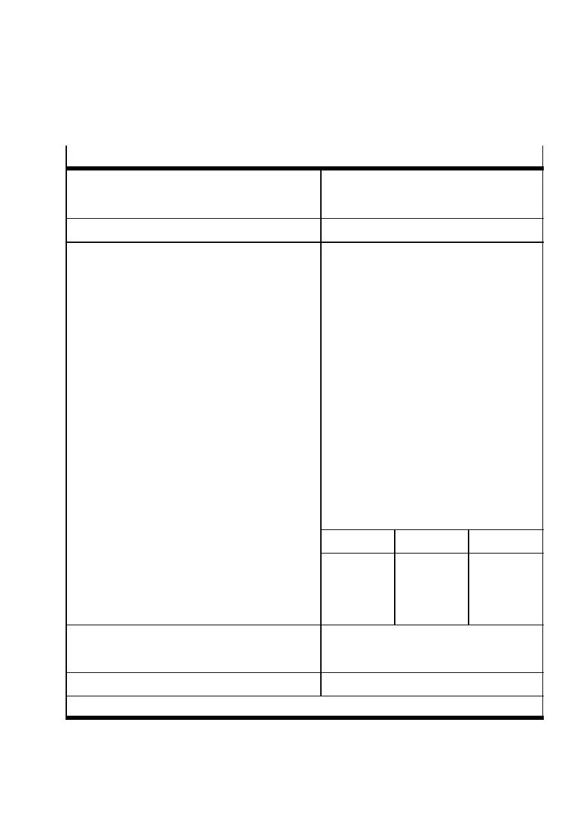
Proportional pressure regulator 2 bar type 6 bar type 10 bar type
Input pressure
1)
Control range
Control accuracy:
Standard (2%)
Class S1 (1%)
max. 4 bar
0,02 ... 2
0.045 bar
0.025 bar
max. 8 bar
0,06 ... 6
0.135 bar
0.075 bar
max. 11 bar
0,1 ... 10
0.225 bar
0.125 bar
Nominal size of proportional pressure regulator:
Pressurization
Exhausting
6 mm
4.5 mm
Manual override locking or non−locking
1)
The input pressure p1 must be at least 1 bar over output pressure p2.
Tab.A/4: Medium and pressure range
 Loading...


