2. Fitting
2−7
Festo P.BE−MPA−EN en 0910d
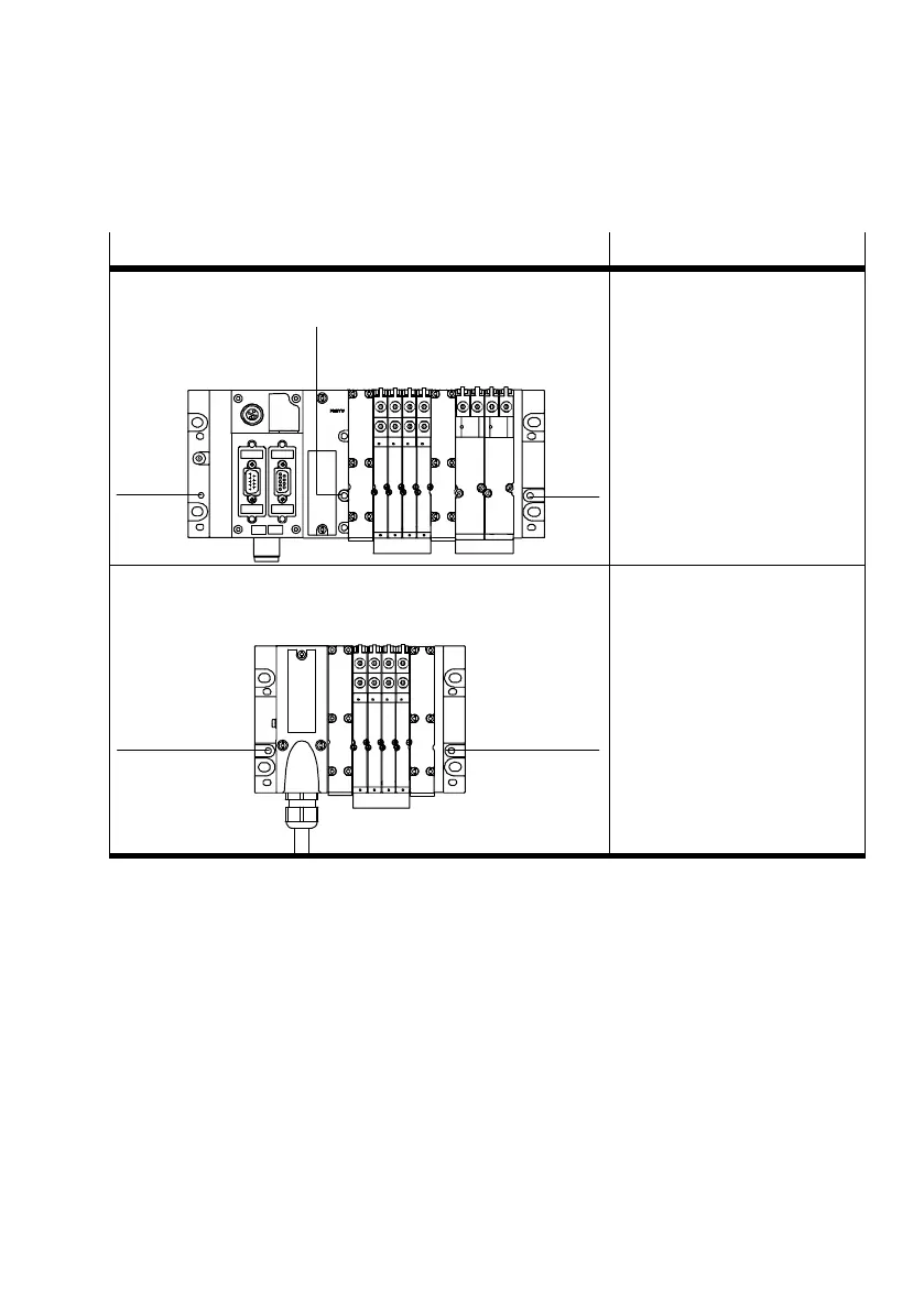
Variant Fastening points
1
1
MPA−S valve terminal with CPX terminal
2
Required mounting of the H−rail
clamping units:
In the end plates:
each with one M4 screw 1
In the pneumatic interface:
with an M4 screw 2
1
MPA−S valve terminal with multi−pin plug connection
1
Required mounting of the H−rail
clamping units:
In the right−hand end plate
and the multiple connector
plate:
each with one M4 screw 1
Tab.2/2: Required mounting points for H−rail mounting
Mounting Proceed as follows:
1. Make sure that the fastening surface can support the
weight of the MPA−S valve terminal
(weightsseeappendixA, Tab.A/1).
2. Mount the H−rail (DIN mounting rail EN 60715 − 35x7.5;
width 35 mm, height 7.5 mm). Make sure there is
sufficient space for connecting the power supply cables
and tubing.
3. Fasten the H−rail to the mounting surface at intervals of
approx. every 100 mm.
 Loading...


