2. Fitting
2−8
Festo P.BE−MPA−EN en 0910d
4. Mount the H−rail clamping units at all required mounting
points (see Tab.2/2).
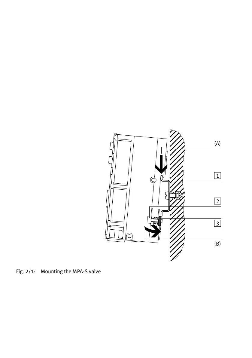
5. Hang the MPA−S valve terminal onto the H−rail
(seeFig.2/1, arrow A).
6. Swing the MPA−S valve terminal onto the H−rail
(seeFig.2/1, arrow B). Make sure that the clamping
component lies horizontally with respect to the H−rail.
1 H−rail
2 Retaining screw
of the H−rail
clamping unit
3 Clamping
component of the
H−rail clamping
unit
ÔÔ
ÔÔ
ÔÔ
ÔÔ
ÔÔ
ÔÔ
ÔÔ
ÔÔ
ÔÔ
ÔÔ
ÔÔ
ÔÔ
ÔÔ
ÔÔ
ÔÔ
ÔÔ
(A)
(B)
1
2
3
Fig.2/1: Mounting the MPA−S valve terminal onto an H−rail
7. Fasten the MPA−S valve terminal, as with the CPX terminal,
against tilting or sliding by tightening the locking screw
with 1.3 Nm.
 Loading...


