Festo — MS6(N)-SV-...-E-10V24 — 2021-11e
The multi-pin plug socket NECA-…-MP1 can be used for static and clocked safety outputs.
–
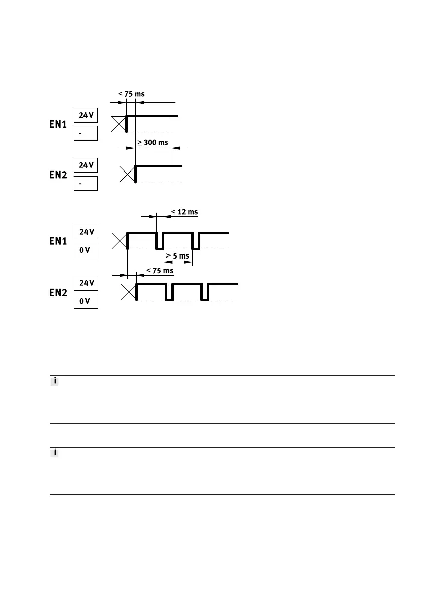
static enable signals (EN1/EN2 = 24 V)
Fig. 4: Static enable signals – signal distance
Fig. 5: Enable signals – detection of shorts across contacts
– clocked enable signals (EN1/EN2 = 24 V) for detection of shorts across contacts.
Detection of shorts across contacts by clock signals is always carried out by the safety relay unit/
safety PLC.
Switching characteristics diagrams
è
Fig. 20.
The clock outputs of different controller manufacturers are not standardised. The usability must be
checked in every case. If the clock pulse is outside the described limits, this is recognised by the
product as an error and a safe switch-off is carried out.
MS6-SV-E with multi-pin plug socket NECA-S1G9-P9-MP3
The multi-pin plug socket NECA-S1G9-P9-MP3 is intended for conventional circuitry with electrome-
chanical safety relays. If problems arise in use with bipolar semiconductor outputs, use the multi-pin
plug socket NECA-S1G9-P9-MP5.
 Loading...