Festo — MS6(N)-SV-...-E-10V24 — 2021-11e
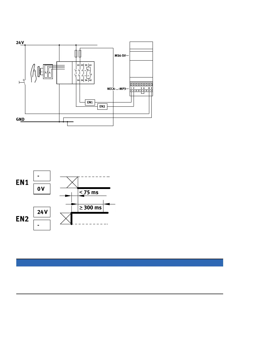
Fig. 6: Connection with NECA-…-MP3
– static enable signals with opposite potentials
– Time delay of the level change of the enable signals is monitored
–
Behaviour on detection of a cross circuit:
– Product in exhausted status: remains in safe status and switches to malfunction
– Product in pressurised status: switches to safe status and to malfunction
Fig. 7: Static enable signals – signal distance
Switching characteristics diagrams
è
Fig. 23.
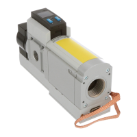
MS6-SV-E with multi-pin plug socket NECA-S1G9-P9-MP5
NOTICE
A cross circuit between the enable signals EN1/EN2 is not detected and does not cause an error
response. The system is pressurised only if the enable signals are applied correctly.
• Ensure that detection of shorts across contacts is established and guaranteed by corresponding
measures in the peripherals (PLC/safety control) in accordance with the valid safety standards.
 Loading...