Festo — MS6(N)-SV-...-E-10V24 — 2021-11e
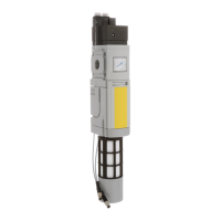
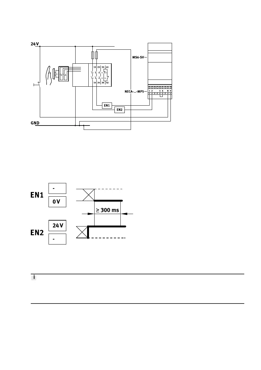
Fig. 8: Connection with NECA-…-MP5
– static enable signals with opposite potentials
– Time delay of the level change of the enable signals is not monitored
–
Behaviour on detection of a cross circuit (by upstream safety relay unit/PLC):
–
MS6-SV- E in exhausted status: remains in safe status and does not go into malfunction
– MS6-SV- E in pressurised status: goes into safe status and does not go into malfunction
–
Enable signals are galvanically separated from the supply voltage
Fig. 9: Static enable signals – signal distance
Switching characteristics diagrams
è
Fig. 23.
Switching statuses
The time delay t2 between EN1 and EN2 must be automatically defined. The duration of the delay
is not evaluated. The multi-pin plug socket NECA-MP5 does not enable the product to detect shorts
across contacts.
Signal contact
The signal contact is a potential-free N/O contact of a semiconductor relay. The contact can be picked
up in the feedback circuit of a safety control system through terminals 3 and 4 of the NECA multi-pin
plug socket as required.
 Loading...