Reproduction forbidden without Fibocom Wireless Inc. written authorization - All Rights Reserved.
L850-GL Hardware User Manual Page 25 of 54
3CA Combination
Condition
(LTE FDD 3CA, Full RB)
Average
Current(mA)
3+7+20, 3+7+28
4+5+30, 4+12+30, 4+29+30
5+66+2, 13+66+2
2+2+5, 2+2+13
3+3+7, 3+7+7, 3+3+20
4+4+5, 4+4+13
5+66+66, 13+66+66, 66+66+2, 66+66+66
7+7+28, 3+3+28, 3+3+5, 1+3+3
Band 4 @+22dBm
930
Band 5 @+22dBm
710
Band 7 @+22dBm
950
Band 8 @+22dBm
650
Band 11 @+22dBm
1000
Band 12 @+22dBm
790
Band 13 @+22dBm
700
Band 19 @+22dBm
690
Band 20 @+22dBm
730
Band 21 @+22dBm
890
Band 28 @+22dBm
670
Band 30 @+21dBm
910
Band 66 @+22dBm
820
Note:
The data above is an average value obtained by testing some samples.
3.3 Control Signal
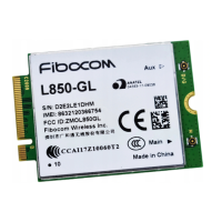
The L850 module provides two control signals for power on/off and reset operations, the pin defined as
shown in the following table:
Pin Pin Name I/O Reset Value Functions Type
6
FULL_CARD_POWER
_OFF#
I
PU
Module power on/off input,
internal pull up
Power on: High/Floating
Power off: Low
3.3/1.8V
67 RESET# I
-
WWAN reset input, internal pull
up(10KΩ), active low
1.8V
50 PERST# I T
Asserted to reset module PCIe
interface default. If module went into
core dump, it will reset whole
CMOS
3.3V


 To Next Page