Reproduction forbidden without Fibocom Wireless Inc. written authorization - All Rights Reserved.
L850-GL Hardware User Manual Page 38 of 54
interference. If it is difficult for the layout, the whole SIM signal lines should be wrapped with
GND as a group at least.
The filter capacitors and ESD devices for SIM card signals should be placed near to the SIM
card slot, and the ESD devices with 22~33pF capacitance should be used.
3.6 Status Indicator
The L850 module provides three signals to indicate the operating status of the module, and the status
indicator pins as shown in the following table:
Pin Pin Name I/O Reset Value Pin Description Type
10 LED1# O PD
System status LED, drain output.
CMOS 3.3V
23 WOWWAN# O PU
Module wakes up Host (AP),Reserved
CMOS 1.8V
48 TX_BLANKING O PD
PA Blanking output, external GPS
control signal,Reserved
CMOS 1.8V
3.6.1 LED#1 Signal
The LED#1 signal is used to indicate the operating status of the module, and the detailed description as
shown in the following table:
Module Status LED1# Signal
RF function ON Low level (LED On)
RF function OFF High level (LED Off)
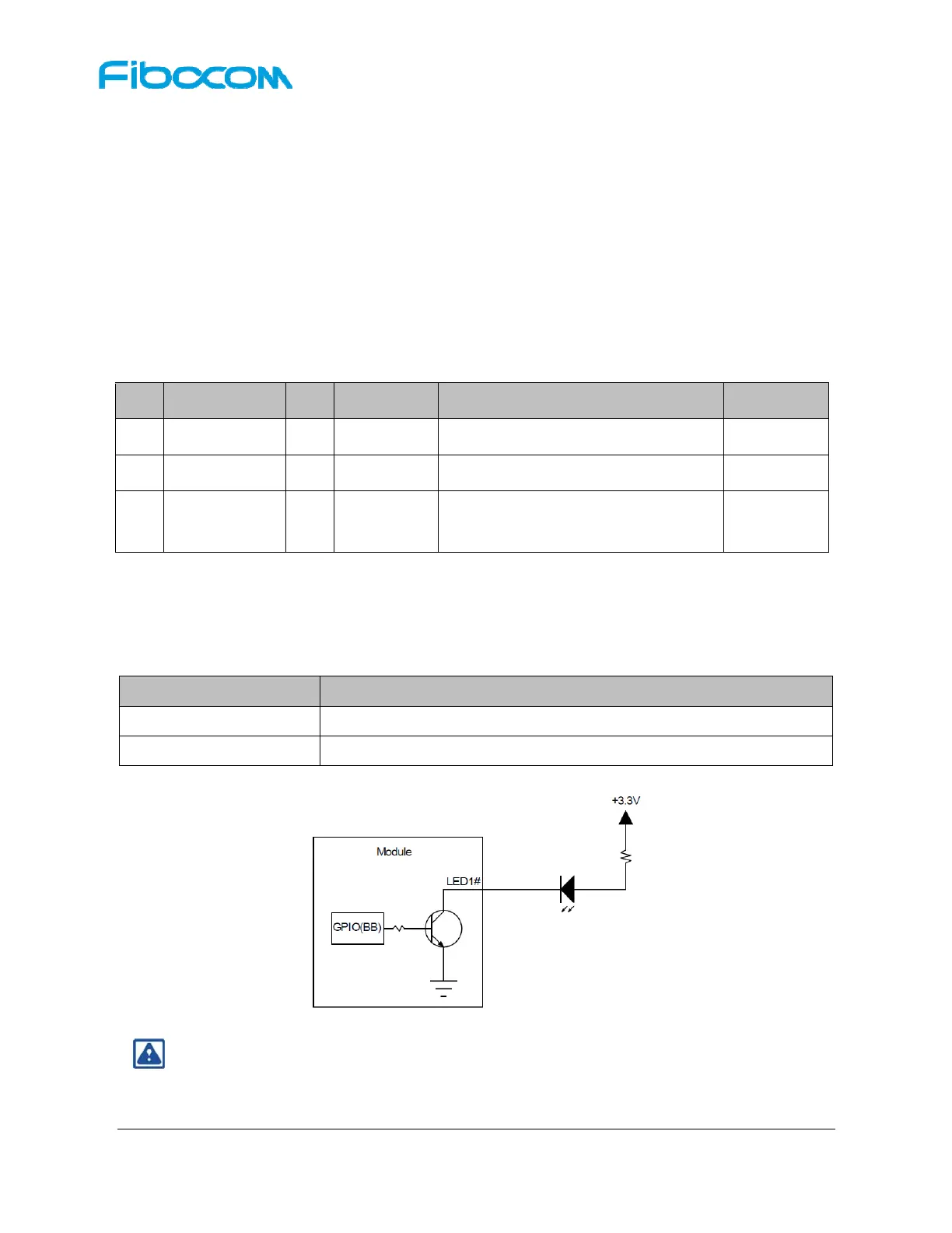
The LED driving circuit is shown in figure 3-18:
Figure 3-18 LED Driving Circuit
Note:
The resistance of LED current-limiting resistor is selected according to the driving voltage and
the driving current.
 Loading...