TWINFLEX
®
pro² Control Panel Engineering and Commissioning Manual
11
Control Panel Connections
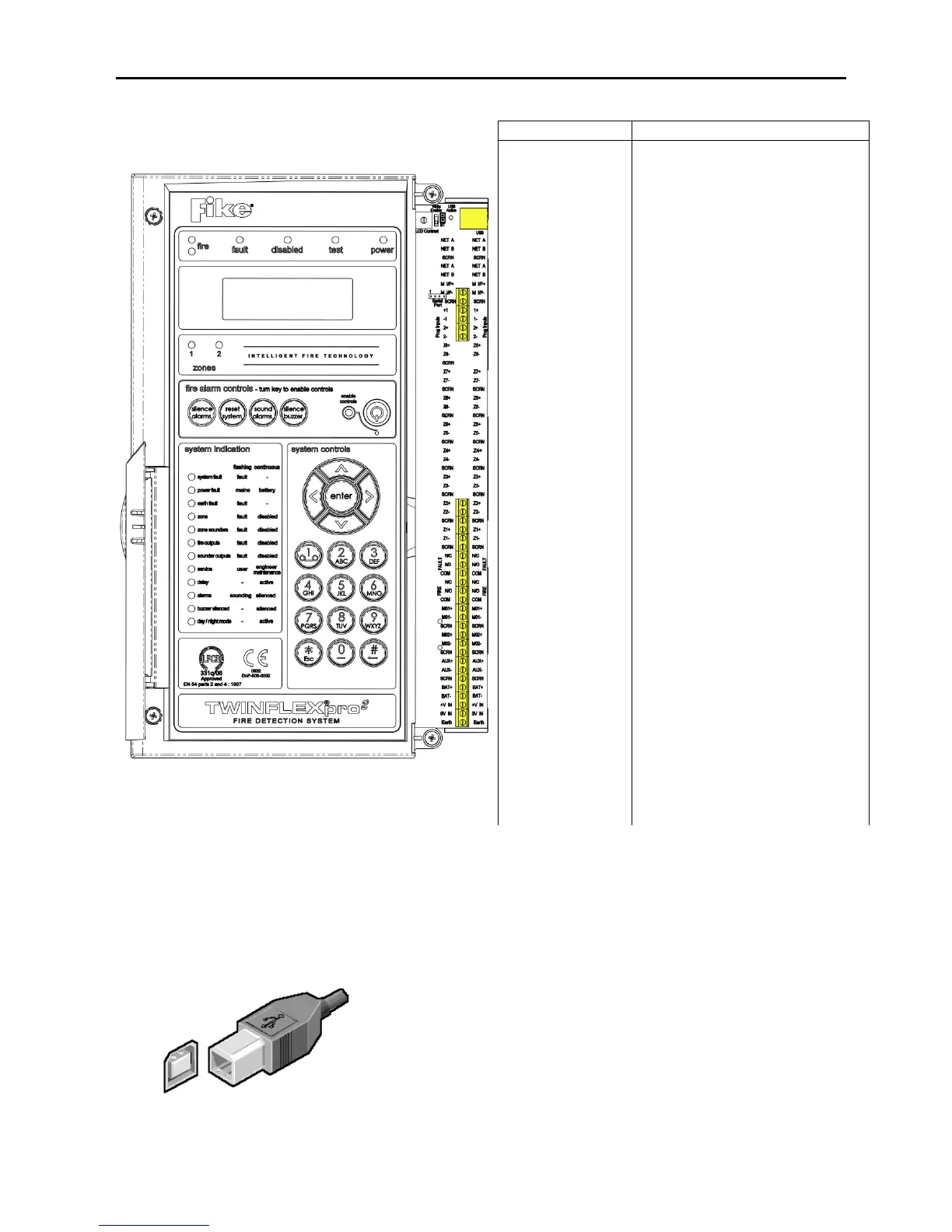
Overview- 2 zone panel
The above diagram shows the terminals for the 2
zone version of the TWINFLEX®pro² panel.
Note: References to voltages are nominal values,
batteries may be 3.2Ah/3.4Ah
USB-B
The panel is fitted with an onboard USB-B connector. This is to provide
communication via a suitable USB lead to a PC for programming of
panel options using the TWINFLEX®pro² OSP configuration software.
USB-B CONNECTION FOR PC LINK
Monitored Input positive connection
Monitored Input 0V connection
Field cable screen connection
Programmable Input positive connection
Programmable Input 0V connection
Device zone positive connection
Device zone 0V connection
Field cable screen connection
Normally closed fault contact
Normally open fault contact
Normally closed fire contact
Normally open fire contact
Monitored Output positive connection
Monitored Output 0V connection
Field cable screen connection
Aux power positive connection
Field cable screen connection
24V DC 3.3Ah Battery positive connection
24V DC 3.3Ah Battery 0V connection
24V DC Input from Switch Mode PSU
0V DC Input from Switch Mode PSU
Earth input from Switch Mode PSU
www.acornfiresecurity.com
www.acornfiresecurity.com