TWINFLEX
®
pro² Control Panel Engineering and Commissioning Manual
14
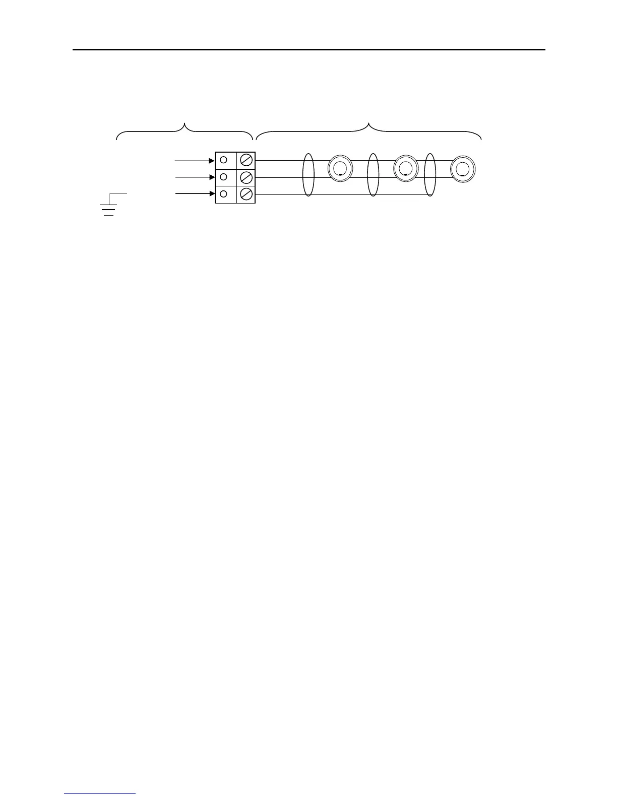
Twinflex Device Zones: Z1 - Z8:
Each zone requires a separate 2-core radial circuit from the control panel to the furthest point of the
zone, to a maximum of 500 metres.
In order to protect against possible data corruption it is important to ensure the following points are
adhered to:
1. The cable screen must be connected to the SCRN terminal at the control panel only.
2. The cable screen must not be connected to earth/ground at any point other than the control
panel (at the SCRN terminal provided, not at any earthing point). Do not connect the
screen to any device back box used other than those supplied by Fike.
3. The cable screen continuity must be maintained at every point of the circuit, using the
terminals provided or a suitable connection block.
4. Do not use a 4-core cable as a circuit zone in and zone out, due to the possibility of data
corruption. It is essential that two 2-core screened cables are used if this is required.
No EOL resistor or unit should be fitted to terminate the cable, this function is performed via DIL switch
1 on the last device.
If a zone is NOT used it MUST be switched off using the zone status menu in the engineers
programming options.
MAXIMUM NUMBER OF DEVICES PER ZONE
Must not exceed 32 devices dependant on Device Loading Units (DLUs) not exceeding the stated
maximum loading. To ensure the maximum loading is not exceeded, use the TWINFLEX®pro² Panel
Battery & Loading Unit Calculation Sheet (document no. 26-1116).