EasyManua.ls Logo

Fike Twinflex pro2 - Input;Output and Zone Configuration

Fike Twinflex pro2
80 pages
Print Icon
To Next Page IconTo Next Page
To Previous Page IconTo Previous Page
Loading...
TWINFLEX
®
pro² Control Panel Engineering and Commissioning Manual
13
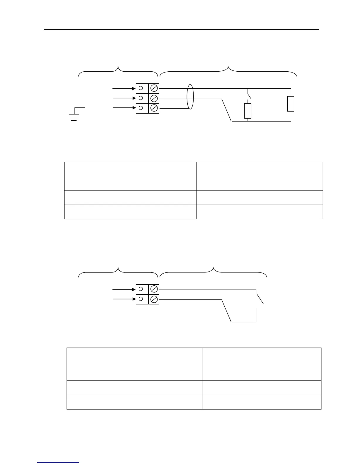
Monitored Input: MI1+, MI1-, SCRN
Maximum Voltage at contacts, 3.3 Volts. Maximum current 10mA.
Monitored Input 1 may be configured to monitor for open and short circuit faults using a 3k3 EOL
resistor and to activate an alarm using a 680 ‘firing’ resistor. It may be configured from the engineer
menu to the following options:
CONTROL EVENT
SILENCE ALARMS
DISABLEMENT
DISABLE SOUNDERS
RESET SYSTEM
DISABLE REM FIRE
SOUND ALARMS
DISABLE SNDR/REM FIRE
SILENCE BUZZER
DISABLE BUZZER
REMOTE FIRE EVENT
REMOTE FIRE - FULL
DAY/NIGHT MODE
INPUT ON
REM FIRE, NO RELAY
INPUT OFF
TECHNICAL EVENT
LATCH
INPUT NOT USED
INPUT OFF
NON-LATCH
Monitored Input 1 is an ancillary function and is not required by EN 54-2.
Programmable Inputs 1 and 2:
Maximum Voltage at contacts, 3.3 Volts. Maximum current 10mA.
Inputs 1-2 are Un-monitored and require a normally closed contact to operate. They may be configured
from the engineer menu to the following options:
Programmable Inputs 1 & 2 are ancillary functions and are not required by EN 54-2
Caution the use of an input to disable the buzzer does not meet EN54-2
CONTROL EVENT
SILENCE ALARMS
DISABLEMENT
DISABLE SOUNDERS
RESET SYSTEM
DISABLE REM FIRE
SOUND ALARMS
DISABLE SNDR/REM
FIRE
SILENCE BUZZER
DISABLE BUZZER
REMOTE FIRE EVENT
REMOTE FIRE - FULL
DAY/NIGHT MODE
INPUT ON
REM FIRE, NO RELAY
INPUT OFF
TECHNICAL EVENT
LATCH
INPUT NOT USED
INPUT OFF
NON-LATCH
ON BOARD PCB
FIELD CONNECTIONS
MI1 -
MI1 +
3k3 EOL
SCREEN
SCREEN
680Ω
N/O CONTACT
ON BOARD PCB
FIELD CONNECTIONS
1 -
1 +
NO CONTACT
www.acornfiresecurity.com

Table of Contents

Related product manuals