TWINFLEX
®
pro² Control Panel Engineering and Commissioning Manual
75
Cable Continuity & Insulation Test Results
After installation of the cable, and termination into all the relevant back-boxes, install a wire link
between the zone +ve and –ve connections at the last device in order to be able to take cable continuity
readings, removing it to take insulation readings. Make sure that all the cables are dressed smoothly
and neatly into their back-boxes in order that they will not be disturbed after the readings are taken.
The commissioning engineer will require these readings, along with correctly marked ‘as-wired’
drawings, before attending site to commission the system.
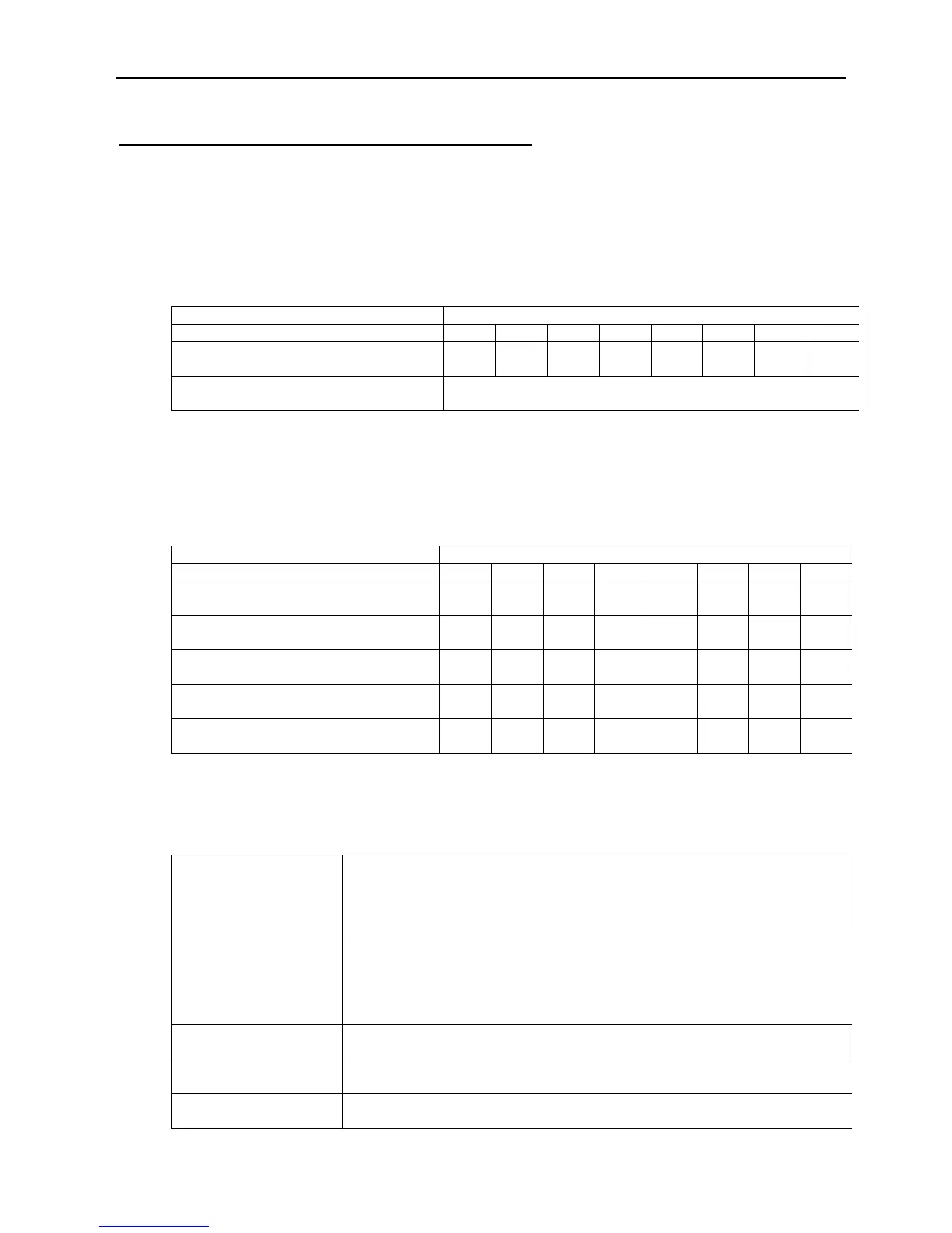
Continuity Reading (ohms)
Zone +ve to –ve with a temporary link
at the last device.
A reading of approximately 1 ohm per 100 metres of 1.5 mm
2
cable is expected and any significant
variation from this should be investigated. If the above readings are satisfactorily showing circuit
continuity then you may also take the reading below, remembering to remove your temporary link at the
last device.
Insulation Reading ( M ohms)
Screen to mains Earth: with scrn
disconnected from panel
A reading in excess of 1M ohm is expected and any significant variation from this should be
investigated. If the readings are satisfactory then the zone wiring is largely proven other than for faults
such as complete polarity reversal.
www.acornfiresecurity.com
www.acornfiresecurity.com