TWINFLEX
®
pro² Control Panel Engineering and Commissioning Manual
9
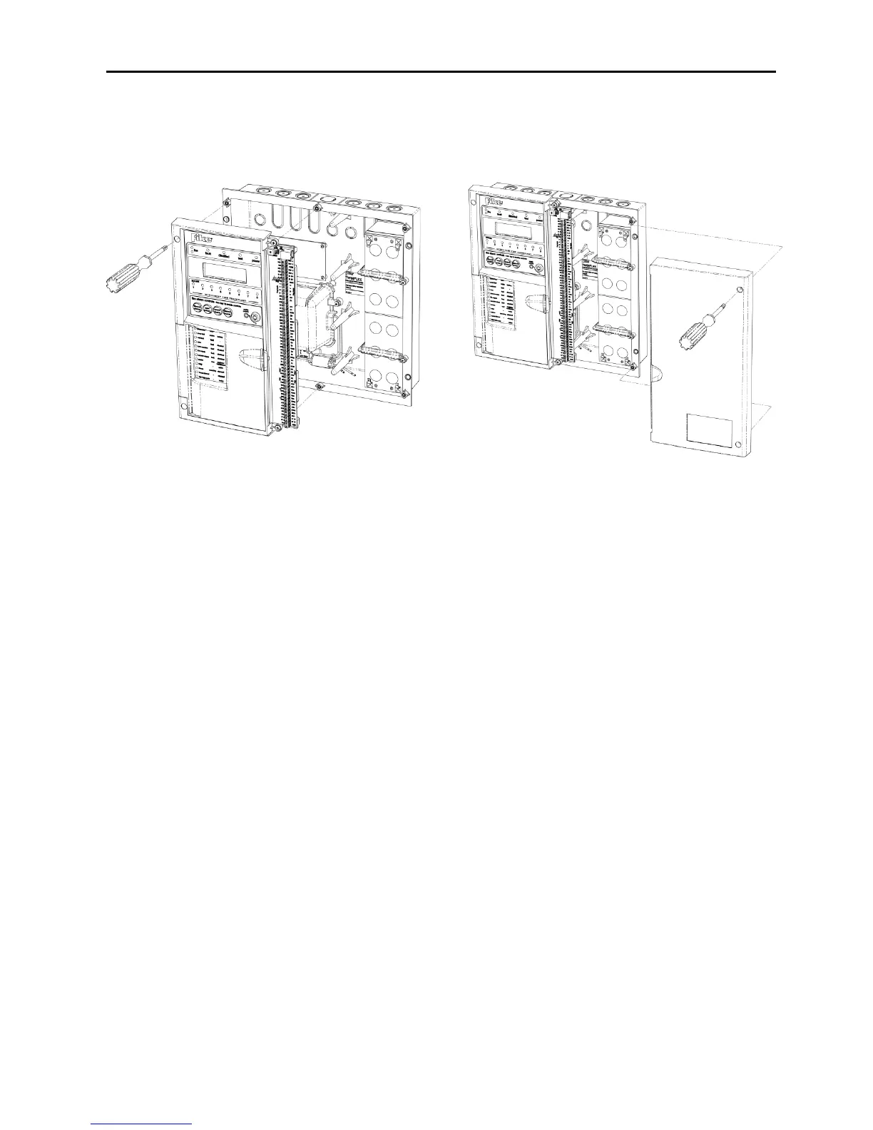
General Assembly
All Panels
Topology & Cabling
All system wiring should be installed to comply with BS 5839: Pt 1: 2017 and BS 7671 (wiring
regulations) and any other standards relevant to the area or type of installation. A cable complying with
the BS 5839: Pt 1: 2017 Category 1 (cables required to operate for prolonged periods during fire
conditions) is required. This must be a 2-core 1.5mm
2
screened fire resistant cable (ie. FP200, Firetuff,
Firecell, Lifeline or equivalent).
Each zone requires a separate 2-core radial circuit from the control panel to the furthest point of the
zone, to a maximum of 500 metres.
In order to protect against possible data corruption it is important to ensure the following points are
adhered to:
1. The cable screen must be connected to earth/ground at the control panel only.
2. The cable screen must not be connected to earth/ground at any point other than the control
panel (at the SCRN terminal provided, not at any earthing point). Do not connect the
screen to any device back box used other than those supplied by Fike.
3. The cable screen continuity must be maintained at every point of the circuit, using the
terminals provided or a suitable connection block.
4. Do not use a 4-core cable as a circuit zone in and zone out, due to the possibility of data
corruption. It is essential that two 2-core screened cables are used if this is required.
Refer to the following System Wiring Schematic for further details.