TWINFLEX
®
pro² Control Panel Engineering and Commissioning Manual
17
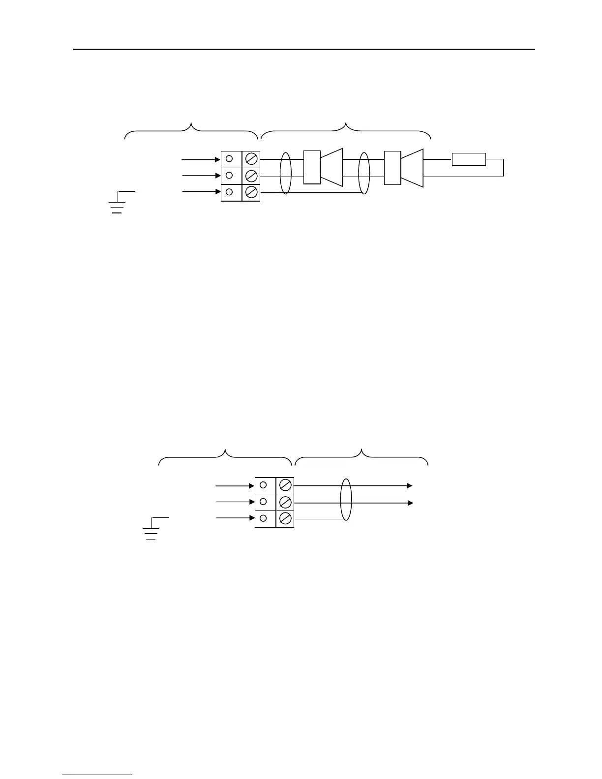
Monitored Outputs 1 and 2: MO+, MO-, SCRN
Outputs 1 and 2 are monitored circuits which may be configured to monitor for open and short circuit
faults with a 10k EOL resistor.
The default setting for outputs 1 and 2 cause the circuits to operate as Common Fire Sounder
Circuits, where the outputs step up to nominally 28V DC in the alarm condition. Various other states
listed below may also be set from the engineers menu. The maximum output current for each output is
250mA for a 2 – 4 zone panel, 200mA for an 8 zone panel. These outputs are protected by a 300 mA
trip polyfuse.
Auxiliary Power: AUX+, AUX-, SCRN
An auxiliary nominal 24V DC power supply is available to power ancillary devices requiring up to 30V
DC.
Note: The auxiliary power supply output will be approximately 30-31V DC when the panel is running
from a mains supply and between 22 and 27V when running from the batteries in a mains failure
condition.
The maximum output current is 250mA. The Auxiliary Power is protected by a 300 mA trip polyfuse
fuse.
It is suggested that additional Power Supply Units be installed to provide power for additional loads.