TWINFLEX
®
pro² Control Panel Engineering and Commissioning Manual
12
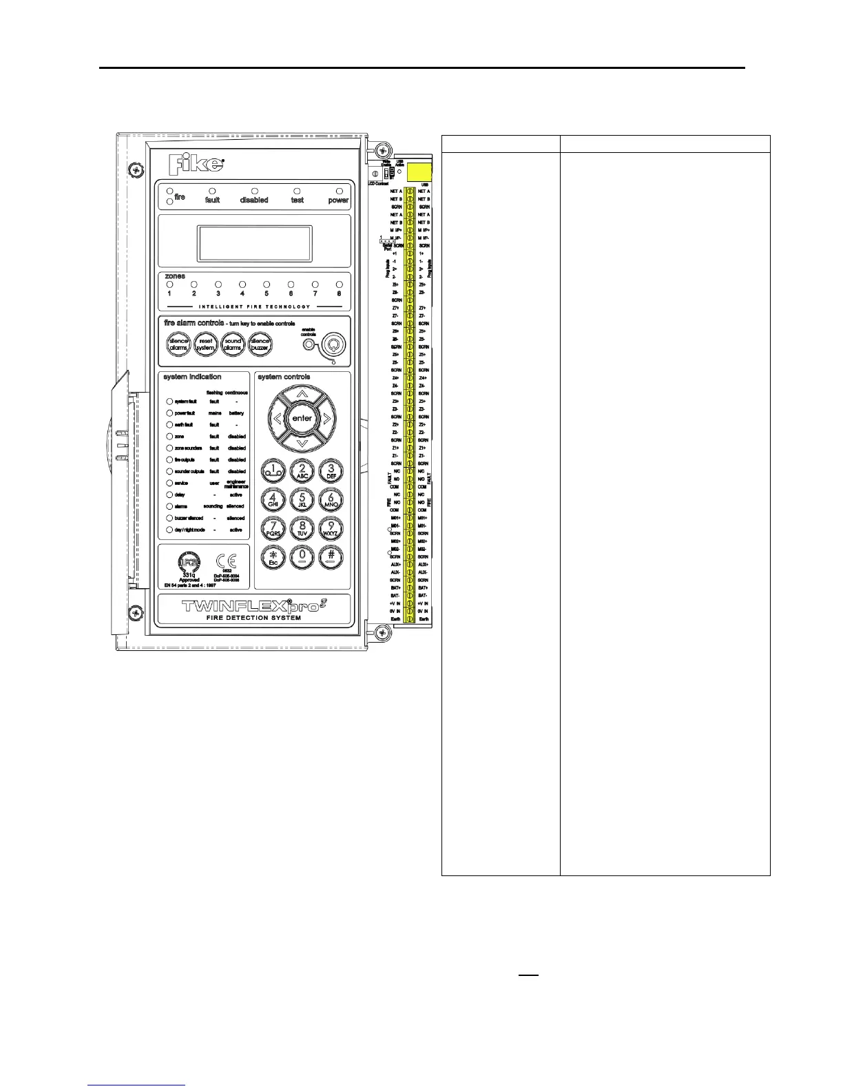
Overview – 4 / 8 zone Panel
The above diagram shows the terminals for the 4 zone /
8 zone version of the TWINFLEX®pro² panel.
Note: References to voltages are nominal values,
batteries may be 3.2Ah/3.4Ah
Network: NET A, NET B, SCRN
NET A & B is an RS485 buss and can communicate with ancillary equipment.
Note: The RS485 Bus can only be used on 4 & 8 zone panels & will not work on 2 zone panels.
Refer to the ancillary equipment manuals for network connections.
Note: Ancillary equipment e.g. repeaters connected to the network do not meet EN 54-2 requirements.
USB-B CONNECTION FOR PC LINK
Peripheral Bus Connections
Peripheral Bus Connections
Peripheral Bus Connections
Peripheral Bus Connections
Peripheral Bus Connections
Peripheral Bus Connections
Monitored Input positive connection
Monitored Input 0V connection
Field cable screen connection
Programmable Input positive connection
Programmable Input 0V connection
Device zone positive connection
Device zone 0V connection
Field cable screen connection
Normally closed fault contact
Normally open fault contact
Normally closed fire contact
Normally open fire contact
Monitored Output positive connection
Monitored Output 0V connection
Field cable screen connection
Aux power positive connection
Field cable screen connection
24V DC 3.3Ah Battery positive connection
24V DC 3.3Ah Battery 0V connection
24V DC Input from Switch Mode PSU
0V DC Input from Switch Mode PSU
Earth input from Switch Mode PSU
www.acornfiresecurity.com
www.acornfiresecurity.com