Functionality Check - 50 BTO Brush Deck
Conventions:
+V
b
: Positive voltage of the battery.
−V
b
: Negative voltage of the battery.
The emergency button is not pressed, the key contact is closed and the charger is not connected to the
mains.
The Brush Deck is in working condition.
Input/output:
Satisfied condition Pin V at work V at rest
Brush Motor Activated XE(1) ref to XE(2) +V
b
−V
b
Display Negative J1(4) ref to B- −V
b
−V
b
Display Transmission J1(7) ref to B- +V
b
−V
b
Display Receiving J1(3) ref to B- +V
b
−V
b
Display Positive J1(8) ref to B- +V
b
+V
b
Electrobrake Activated J2(1) ref to J2(2) +V
b
−V
b
Traction pedal pressed J5(3) ref to J5(6) +V
b
−V
b
Operator Seated J7(15) ref to J7(1) +V
b
−V
b
Brushes Actuator in motion J14(1) ref to J14(4) +V
b
−V
b
Brushes Actuator ALL OUT J14(2) ref to J14(6) −V
b
+V
b
Brushes Actuator ALL IN J14(5) ref to J14(6) −V
b
+V
b
Maximum pressure limit switch pressed J14(3) ref to J14(6) −V
b
+V
b
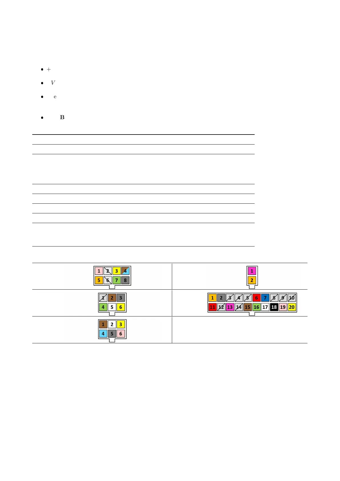
J1 J2
J5 J7
J14
6.6.2 Relative electrical Components
Orbital Brush Motor
The motor is a DC type with permanent magnets, connected directly to the function board via a connector.
With a constant 24 V DC supply (full battery) the single brush motor (M2) draws 1.7 Amps ± 0.1. With a
constant 21 V DC supply (low battery) the absorption is 1.6 Amps ± 0.1.
Actuator
The actuator, by means of the lever and the tie rod, lowers the brush deck, moves it sideways and pushes to
the ground.
77
 Loading...