Functionality Check - Water Unit
Conventions:
+V
b
: Positive voltage of the battery.
−V
b
: Negative voltage of the battery.
The emergency button is not pressed, the key contact is closed and the charger is not connected to the
mains.
The Water system is in working condition.
Input/output:
Satisfied condition Pin V at work V at rest
Display Negative J1(4) ref to B- −V
b
−V
b
Display Transmission J1(7) ref to B- +V
b
−V
b
Display Receiving J1(3) ref to B- +V
b
−V
b
Display Positive J1(8) ref to B- +V
b
+V
b
Electrobrake activated J2(1) ref to J2(2) +V
b
−V
b
Traction pedal pressed J5(3) ref to J5(6) +V
b
−V
b
Backward activated J7(11) ref to J7(16) +V
b
−V
b
Seated Operator J7(15) ref to J7(1) +V
b
−V
b
FSS/FLR activated J7(17) ref to J1(8) −V
b
+V
b
Solution Tank Floater J7(2) ref to J7(1) +V
b
−V
b
Water Pump Activated J8(3) ref to J8(1) +V
b
−V
b
Solenoid Valve activated J11(13) ref to J11(5) +V
b
−V
b
Solution tank recycle solen. Valve J11(6) ref to J8(2) +V
b
−V
b
Recovery tank recycle solen. Valve J11(3) ref to J8(2) +V
b
−V
b
Chemical Pump activated J11(8) ref to J11(9) +V
b
−V
b
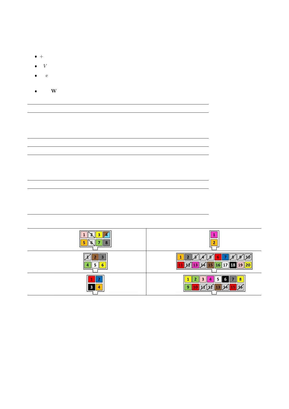
J1 J2
J5 J7
J8 J11
9.5.1 Relative electrical Components
Water Pump
The water pump, connected to the solution tank and to the solenoid valve, allows a regular flow to the brushes.
Solenoid Valve
The solenoid valve is located on the back of the brush deck body, which can be easily accessed from the left
side.
99


 To Next Page