EN
111
8.2.4.9 Discharge of the capacitor
Wait the internal capacitors to be discharged.
WARNING – B The discharge time of the stored energy is
indicated on the regulatory label.
8.2.4.10 Voltage absence test on DC side (wiring box)
WARNING – B Before to approach the below operations
all the steps from 1 to 9 included must be successfully
completed.
STANDARD and -S2 MODELS (1/2 MPPTs):
• Open the wiring box front cover (07) (refer to paragraph “Opening
the wiring box cover”)
• Visually inspect the components to identify the presence of
any overheating, signs of electric arcs, failure of the insulating
devices, loosen connections or cables not connected.
• Test the absence of voltage on the DC inputs using the voltage
detector: the voltage absence test on DC side must be carried
out through the openings on the DC protective shield (60), as
shown in the picture.
60
CH1 Negative
CH1 Positive
CH2 Negative
CH2 Positive
• For each input channel the measurement must be performed
between: positive to ground, negative to ground, positive to
negative.
Check sequence: Positive to ground (PE)
First point Second point
CH1(+) PE
CH2(+) PE
Check sequence: Negative to ground (PE)
First point Second point
CH1(-) PE
CH2(-) PE
Check sequence: Positive to negative
First point Second point
CH1(+) CH1(-)
CH2(+) CH2(-)
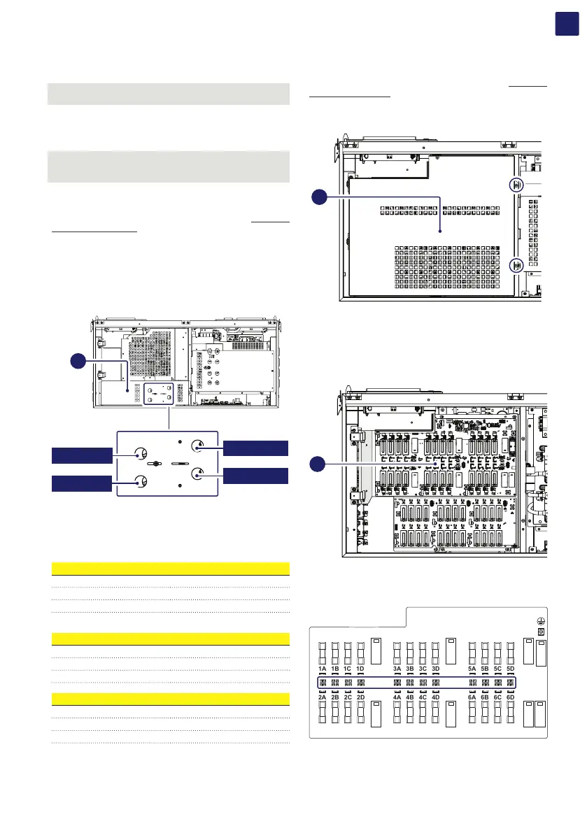
-SX, SY, -SX2, -SY2 MODELS (6 MPPTs):
• Open the wiring box front cover (07) (refer to paragraph “Opening
the wiring box cover”)
• Remove the internal DC Protective shield (60) by removing the
two M5 screws.
60
• Visually inspect the components to identify the presence of
any overheating, signs of electric arcs, failure of the insulating
devices, loosen connections or cables not connected.
• Check that all LEDs of positive side string fuses board (19) are
OFF.
PVS-100_120-TL_B2_S(X-Y)2
19
The layout of the positive side string fuses board (19) with
related LEDs is provided below:
CH1
CH2
CH3
CH4
CH5
CH6
1A
2A
1B
2B
1C
2C
1D
2D
3A
4A
3B
4B
3C
4C
3D
4D
5A
6A
5B
6B
5C
6C
5D
6D