EN
112
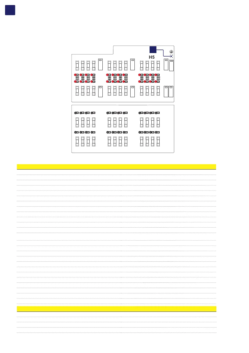
• Test the absence of voltage on the DC inputs using the voltage detector: the voltage absence test on DC side must be carried out on the
positive side string fuses board (19) and on negative side string fuses board (20). The layout of the two boards is provided below, with
reference of the points where the input DC voltage absence test must be performed. The points are represented by the faston where the
cables (coming from DC switches (15)) are connected.
CH1
CH2
CH3
CH4
CH5
CH6
1A
2A
1B
2B
1C
2C
1D
2D
3A
4A
3B
4B
3C
4C
3D
4D
5A
6A
5B
6B
5C
6C
5D
6D
+
+
+
+
+
+
+
+
+
+
+
+
+
+
+
+
+
+
+
+
+
+
+
+
CH1
CH2
CH3
CH4
CH5
CH6
1A
2A
1B
2B
1C
2C
1D
2D
3A
4A
3B
4B
3C
4C
3D
4D
5A
6A
5B
6B
5C
6C
5D
6D
PE
For each input channel the measurement must be performed between: positive to ground, negative to ground, positive to negative.
Check sequence: Positive to ground (PE)
First point Second point
1A (+) PE
1B (+) PE
1C (+) PE
1D (+) PE
2A (+) PE
2B (+) PE
2C (+) PE
2D (+) PE
3A (+) PE
3B (+) PE
3C (+) PE
3D (+) PE
4A (+) PE
4B (+) PE
4C (+) PE
4D (+) PE
5A (+) PE
5B (+) PE
5C (+) PE
5D (+) PE
6A (+) PE
6B (+) PE
6C (+) PE
6D (+) PE
Check sequence: Negative to ground (PE)
First point Second point
1A (-) PE
1B (-) PE
1C (-) PE