EQUIPMENT: FIRECLASS DUO-CEL
PUBLICATION: OM_DUO-CEL_APP
ISSUE No. & DATE: 2 20/06/18
PAGE 27 of 46
11.2 DUO-CEL Repeater Motherboard
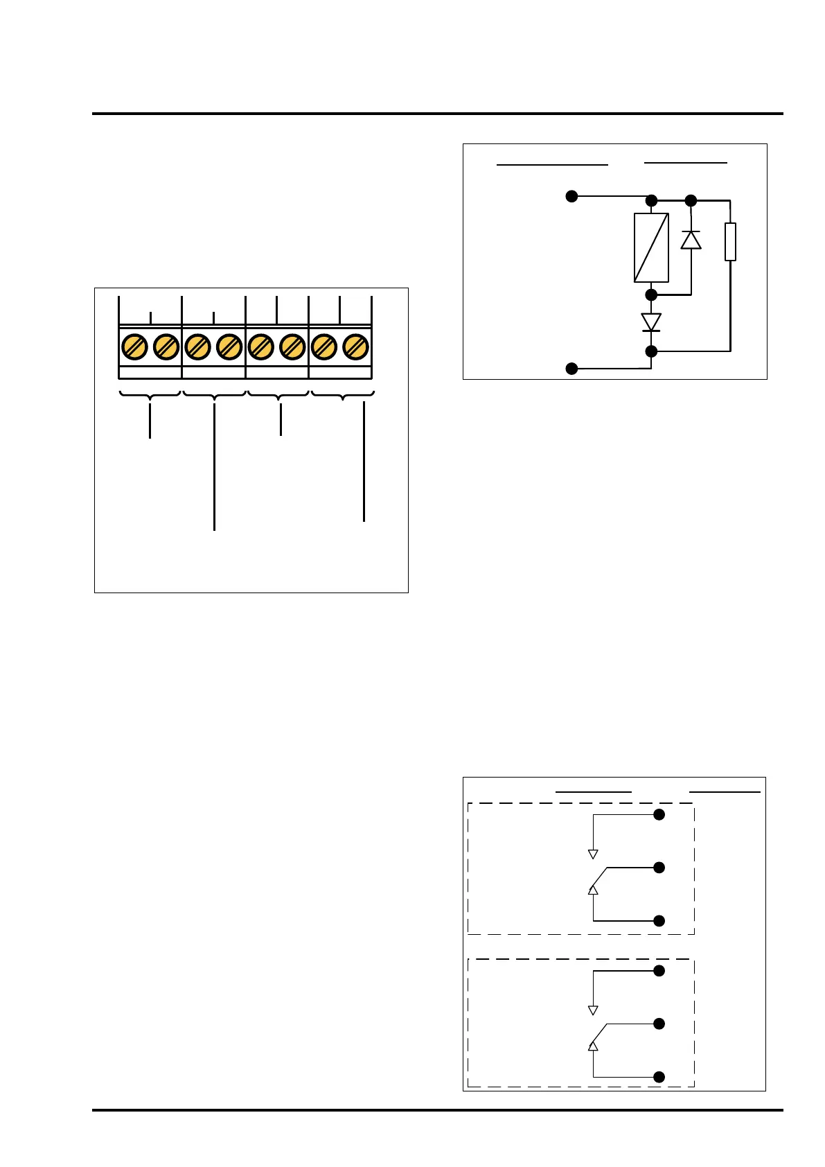
Termination Details
Figure 7 below shows the available field wiring
terminals for the DC powered DUO-CEL Repeater.
The mains AC powered repeater does not have the
two sets of terminals marked 24V & 0V.
Figure 7 – DUO-CEL Repeater field
terminations
RS485
COMMS.
FROM PANEL OR
REPEATER
UNFUSED
24VDC
OUTPUT TO NEXT
REPEATER
(DC powered
repeaters only)
REPEATER
A B BA0V24V
AUX 0.25A
24V 0V
UNFUSED
24VDC
INPUT
(DC powered
repeaters only)
RS485
COMMS.
TO NEXT
REPEATER
11.3 Auxiliary Supply
An auxiliary supply is available to power the
repeaters and other external field equipment from
the panel. This voltage is nominally 27.15VDC but
varies with temperature and during mains-failed
conditions, depending on battery voltage. See
section 14 for details of maximum load.
The output is fused using an electronic device, and
fuse activation will be indicated as Fuse Failed on
the panel display. The fuse can be reset after
clearing the fault by operating the Reset button on
the display.
The auxiliary supply terminals are labelled Aux
0.25A 24V and 0V.
An additional UNFUSED 24V output is provided on
repeaters for connection to additional DC powered
repeaters.
Note: If equipment draws current from the
auxiliary supply during the mains-failed
condition this must be included in the battery
capacity calculations.
11.4 Fire Signal Output
The Fire Signal output is fault-monitored in the non-
energised condition. It is designed to operate a
signalling relay at the routing equipment. The Relay
coil must be polarised and suppressed, because
the 10k end-of-line device is reverse-polarity
monitored for open & short circuit faults. See Figure
8 for details.
Figure 8 – Fire Signal Output Connections
+
-
Field Wiring
Panel Terminals
Output conditions:
Quiescent: -5V DC
[open circuit voltage]
Active [fire]: 24V [nom]
DIODE
1N4002
10k
EOL
DIODE
1N4002
11.5 Fire Relay Output
The Fire Relay output is a single pole relay with
volt-free change over contacts. The relay is
normally de-energised and energises for any fire
alarm condition. The relay remains energised until
panel reset. This relay will not energise if zone 1 is
configured as non-latching and only zone 1 is in
alarm. See Figure 9 for details.
11.6 Fault Relay Output
The Fault Relay output is a single pole relay with
volt-free change over contacts. The relay is fail-safe
and is therefore normally energised, de-energising
for any faults. The marking on the control board
terminals is for the energised condition. See Figure
9 for details.
NOTE:
The volt-free relay contacts are rated at 30Vdc
with a maximum current of 1A. Do not exceed
the rated voltage and current.
Figure 9 – Relay contact connection details
P
N/C
Fire Relay
Fire Relay shown in
de-energised condition.
Field WiringPanel Circuit
N/O
P
N/C
Fault Relay
Fault Relay shown in
energised condition.
N/O