EQUIPMENT: FIRECLASS DUO-CEL
PUBLICATION: OM_DUO-CEL_APP
ISSUE No. & DATE: 2 20/06/18
PAGE 43 of 46
15.7 A1466 Interface Relay
The A1466 Interface Relay board is available as an
optional item.
This relay is compatible with the Fire Signal Output
on the DUO-CEL panel. It provides two sets of volt-
free normally open & normally closed contacts.
Polarity and suppression diodes are also mounted
on the board.
The A1466 board should be mounted inside the
equipment to be controlled by the Fire Signal
output. The 10K EOL resistor should be connected
across the 24V & 0V terminals of the A1466 board..
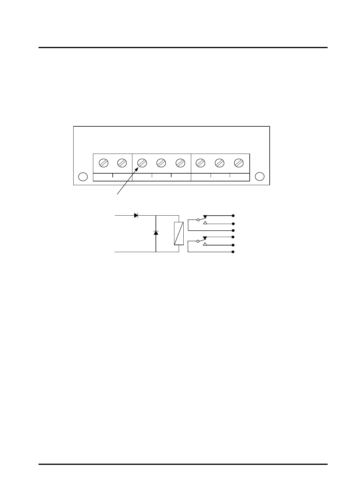
Figure 19 – A1466 Interface Relay Specification
Terminal block
Terminals
Max conductor: 2.5mm.
24V, 0V: Relay coil connections – observe polarity .
P1: Relay contact 1 pole.
N/C: Relay contact 1 normally closed.
N/O: Relay contact 1 normally open.
P2: Relay contact 2 pole.
N/C: Relay contact 2 normally closed.
N/O: Relay contact 2 normally open.
Ratings
Coil: Operating voltage range: 17.5 to 30VDC.
Operating current: 8mA at 24VDC.
Resistance: 2900 Ohms.
Relay contacts: 2A at 30VDC
Warning – Do not exceed the rated voltage or
current.
PCB Layout
24V 0V P1 N/C N/O P2 N/C N/O
CEL A1466 Iss 2
28/1/93
TB1
TB2
TB3
Dimensions
Board size: 30mm x 45mm.
Height: 15mm.
Fixing centres: 24mm x 30mm
Fixing hole sizes: M4 clearance.
Installation
Must be installed within enclosure of
the equipment being controlled.
Environmental: Clean, dry location
not subject to excessive vibration or
shock.
Temperature: -10 to +70 deg C
24VDC
0VDC
TB1
N/C
N/O
P1
N/C
N/O
P2
TB2
TB3
Circuit Diagram
Specification