EQUIPMENT: FIRECLASS DUO-CEL
PUBLICATION: OM_DUO-CEL_APP
ISSUE No. & DATE: 2 20/06/18
PAGE 29 of 46
They are referred to as ‘open collector’ because
each output is connected to the open collector pin
of a transistor.
In the deactivated state, each open collector output
is floating and is effectively open circuit. When the
output is activated, the transistor allows current to
flow from the open collector pin down to 0V. Each
output is able to sink 50mA when active. Higher
currents will damage the transistor driver.
If the output is used to drive a relay then a
suppression diode should be used across the relay
coil to avoid damaging the output driver circuit.
11.8.1 Disabled Output
The Disabled output is activated when any
disablements exist on the panel. The only
exceptions are Buzzer Disable and Earth Fault
Disable, both of which produce no indications on
the panel.
11.8.2 Evacuate Output
The Evacuate output is activated when the panel is
in the Evacuate state, either due to the button on
the display or due to the Remote Control input.
11.8.3 Buzzer Active Output
The Buzzer Active output duplicates the panel
buzzer for alarm and fault conditions. It does not
operate for button presses.
11.9 Sounder Circuits
The DUO-CEL panel has up to 4 standard sounder
circuits, each rated at 0.5 Amps (not including twin-
wire sounders). The circuits are reverse polarity
monitored for open and short circuit faults. All
connected field devices must be polarised to allow
correct fault monitoring. To prevent damage to the
control panel, any solenoid devices such as bells
must also have a suppression diode fitted as shown
in Figure 11.
The circuit must be terminated with a 10K end of
line resistor.
Figure 11 – Alarm circuit configuration
Polarising
diode
[1N4002S]
Suppression
diode
[1N4002S]
Bell
Electronic
sounder
10K
EOL
Resistor
Alarm +
Alarm -
The voltage drop on each alarm circuit should be
calculated to ensure that the minimum voltage at
the end of each circuit exceeds the minimum
required by each sounding device.
The voltage at the end of the circuit is given by the
following calculation:
V
almin
= V
opmin
– (I
al
x 2 x L
al
x R
cable
)
V
almin
= Minimum Alarm Voltage (V)
V
opmin
= Minimum Output Voltage (19.5V)
I
al
= Alarm Current (A)
L
al
= Alarm Circuit length (M)
R
cablel
= Cable Resistance per metre ()
1.5mm
2
– 0.015 per metre per core
2.5mm
2
– 0.009 per metre per core
11.10 Electrical Design of Detection
Zones
To allow the panel to correctly monitor for fault
conditions, the wiring for each zone must be
installed as a continuous pair with no spurs or tees.
The end-of-line monitoring device will depend on
the type of panel. Correct polarity must be strictly
observed throughout.
11.10.1 Standard Panel Default Zone
Configuration
The standard panel zone configuration (factory
Default) uses active fault monitoring, with a 10uF
capacitor as the EOL device (see Figure 13).
11.10.2 Standard Panel Resistor Zone
Configuration
The standard panel can be set to resistor zone
configuration (set by DIL switch). This uses passive
fault monitoring, with a 6K8 to 3K9 resistor as the
EOL device (see Figure 14).
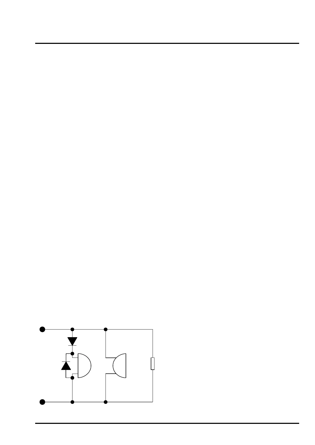
11.10.3 Twin-Wire Panel
The Twin-Wire panel uses passive fault monitoring
but with an EOL device consisting of a zener diode
and resistor as shown in Figure 12. The device is
polarised and should not be connected in reverse
(otherwise the panel will indicate an alarm
condition). This EOL device allows monitoring for
detector head removal whilst maintaining line
continuity via diodes fitted to detector bases.
The addition of the zener and resistor enables the
twin-wire sounders to operate, even with one
detector removed.
Only use detector bases with line continuity diodes
fitted.
DO NOT leave any diode bases empty. Detectors
should be fitted or a blanking plate which links out
the diode should be fitted.
NOTE: The twin-wire EOL will draw up to 4mA from
the zone in quiescent and this should therefore be
added to the total zone current when calculating the
standby battery requirements.