EQUIPMENT: FIRECLASS DUO-CEL
PUBLICATION: OM_DUO-CEL_APP
ISSUE No. & DATE: 2 20/06/18
PAGE 33 of 46
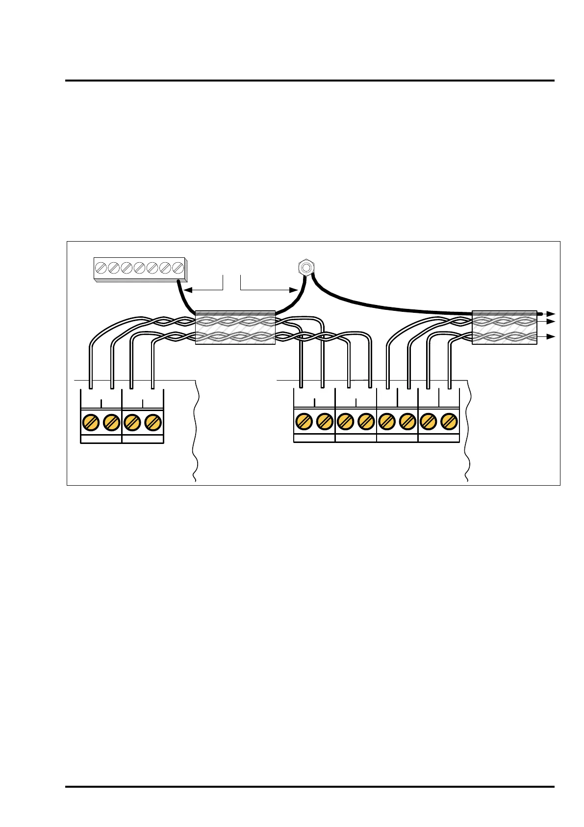
11.11 Panel to Repeater Wiring
The Repeater RS485 communication and 24Vdc
power connections should all be made via a single
multi-core data cable. The number of cores
required is two if the repeater is mains powered, or
four if powered from the panel. A cable screen is
not required but is usually present in most data
cable types. The A & B lines should be connected
via one set of twisted pair cores, the 24V & 0V lines
should be connected via another set of twisted pair
cores.
If the cable includes a screen then this should be
earthed at the panel & all repeaters.
Terminal A at the panel must be connected to
Terminal A at all repeaters, Terminal B at the panel
must be connected to Terminal B at all repeaters.
Figure 18 – Repeater Wiring Diagram
EARTH STUD (Earth Bar may be present instead)
EARTH BAR
Data Cable
Screen
DUO-CEL Panel
REPEATER
A B
AUX 0.25A
24V 0V
REPEATER
A B BA0V24V
AUX 0.25A
24V 0V
DUO-CEL Repeater
To Next Repeater