EQUIPMENT: FIRECLASS DUO-CEL
PUBLICATION: OM_DUO-CEL_APP
ISSUE No. & DATE: 2 20/06/18
PAGE 32 of 46
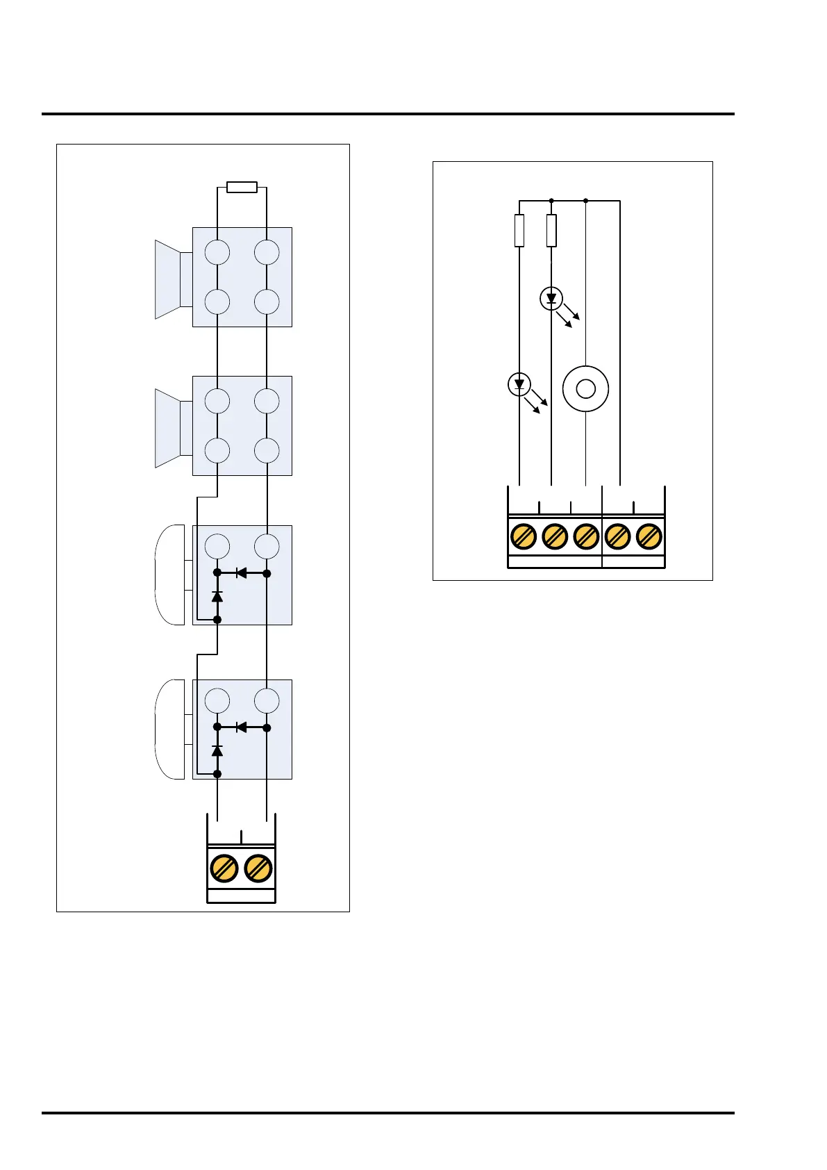
Figure 16 – Alarm Circuit Wiring Diagram
Polarised
Electronic
Sounder
AL1+ AL1–
-
-
+
+
-
-
+
+
-
+
-
+
Polarised
Electronic
Sounder
Solenoid
Driven Bell,
fitted with
polarising &
suppression
diodes
(1N4002)
Solenoid
Driven Bell,
fitted with
polarising &
suppression
diodes
(1N4002)
10K ¼ W
EOL Resistor
NOTE: The Alarm circuit terminals are marked
for the active polarity. When in quiescent
monitoring mode, the alarm circuit is monitored
in the reverse polarity (hence the requirement
for a polarising diode).
Figure 17 – Remote Indicators Wiring
Diagram
DIS.
EVAC.
BUZ.
AUX 0.25A
24V 0V
+
_
Current
Limiting
Resistors
590R
1.5W
minimum
LED
Indicators
Or Lamps
24Vdc
Buzzer,
50mA
maximum
current
REMOTE O/PS